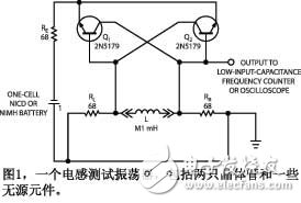
In the absence of expensive test equipment, the circuit of Figure 1 can provide a simple and quick alternative to measuring inductance. Applications include verifying that the inductance value is close to the design parameters and describing the core characteristics of the unknown parameters. By design, the circuit tests most of the inductors used in power supplies, as well as the inductance in many RF circuits.

The circuit consists of two cascaded common-emitter amplifier stages that form an unsaturated cross-coupled flip-flop. A common emitter stage is used as the phase shift, and two cascade stages form a non-inverting feedback amplifier whose gain produces feedback. In the absence of the inductor L to be tested, the feedback occurs in the DC state, and the circuit behaves as a flip-flop, which can take either of two stable states. After connecting the inductor, reduce the DC positive feedback below the feedback level. Therefore, the feedback can only occur in the AC state and the circuit becomes an unstable oscillator.
By minimizing the storage time of the transistor and keeping the transistor in a state of saturation, the operation of the circuit can be accelerated. Almost any type of high-speed, small-signal RF transistor provides a suitable switching speed, although lower frequency devices can operate, but reduce the range of small inductor measurements. The oscillation frequency of the circuit is inversely proportional to the inductance to be measured. You can use a frequency counter or an oscilloscope to measure the oscillation frequency.
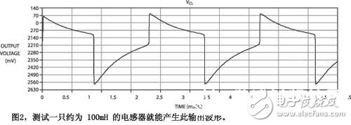
Figure 2 shows a waveform generated by an inductor of approximately 100mH. The oscillation frequency depends on the L/R time constant formed by the inductance to be tested and the resistances RL and RR. The time it takes for the waveform to change its state is proportional to the value of the inductance.
For the half cycle, it is approximately THALF = "L/100". The entire period of the oscillation cycle is twice this value, or TFULL = "L/50". Calculate the inductance value, L = 50 & TImes; TFULL. Alternatively, the frequency is inversely proportional to the inductance value, or fOSC = 50/L. The frequency counter can be used to measure the inductance as L=50/fOSC.
The finite switching speed of the circuit is approximately 10 ns, so its measurement range has a low limit of 1 mH. A method of connecting a small inductor in series with a large inductor can be used to record the reading, measure the individual value of the larger inductor, and then subtract the two measured values ​​to obtain a small inductance value.
Although the circuit has no upper limit on the inductance value, when the ESR (equivalent series resistance) of the inductor exceeds about 70 Ω, the circuit stops oscillating and turns to bistable operation. The circuit measures the values ​​of various inductors and transformer windings, except for small low-frequency core devices with high ESR. For the highest accuracy, an instrument with a low input capacitance should be used to measure the oscillation frequency.
Powering the circuit is a NiCd (NiCd) or NiMH (NiMH) rechargeable battery. These batteries have relatively flat voltage/time discharge characteristics that improve the measurement accuracy of the circuit. The power consumption of the circuit is only about 6mA during operation.

Sandeep M Satav and VV Rama Sarma, EMI-EMC Centre, RCI, Hyderadad, India
The popular name for magnetic field meters is the “Gaussianâ€, which is not available for many amateurs and engineers on the market for various brands and models. This design example combines a common DMM (Digital Multimeter) with a single semiconductor component to measure magnetic flux density and magnetic field strength.
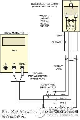
Figure 1 shows the measuring device, which consists of a probe, a battery pack, and a DMM. The active components of the probe consist of a linear Hall effect sensor. Virtually any linear Hall-effect sensor works well in this application, but this probe version uses the Allegro MicroSystems A1323 sensor, which produces a voltage proportional to the applied magnetic field (Reference 1). The A1323 operates from a 4.5V to 5.5V supply and its quiescent output voltage (zero field output) is dependent on 50% of the supply voltage. Given that the A1323's nominal sensitivity is 2.5 mV/gauss, it provides a full-scale range of 1800 Gauss (4.5 volts / 2.5 mV / Gauss = 1800 Gauss) for a 4.5 V supply voltage.

Applying a magnetic field towards the south side of the front side of the sensor increases the output voltage of the sensor, which is proportional to the magnetic field applied perpendicular to the brand side of the sensor, and applying a magnetic field on the north side of the same side results in an output voltage. The proportion is decreasing. For a 4.5V supply, the sensor's 2.25V quiescent output voltage can be increased to 4.5V (for 900 Gauss positive south magnetic field) or reduced to 0
V (for 900 Gauss positive north magnetic field). The sensor detects the strength and polarity of the DC magnetic field, while its AC magnetic field bandwidth extends to 30 kHz.
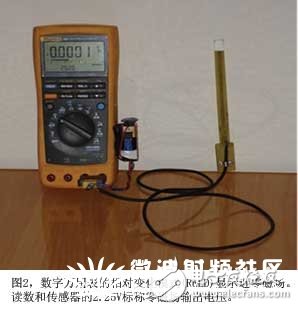
The circuit test board version of the probe contains a small printed circuit board that is long enough to fit the operator's hand (Figure 2). The sensor leads are connected to a high quality three conductor shielded cable and two 10 nF surface mount decoupling capacitors. The sensor's power supply consists of three small 1.5V batteries in series with a total voltage of 4.5V. To achieve a larger full-scale range, a 9V regulator can be used to feed a 5V regulator IC such as a 7805 volt meter with a 9V battery and add an on/off switch when needed. The battery should be placed near the voltmeter. Otherwise the steel casing of the battery will interfere with the observed magnetic field. The 10nF SMD capacitor should be used to decouple the sensor's input and output pins. Although a DMM that provides higher dc accuracy and an AC bandwidth of more than 50 kHz can display the output of the sensor, Fluke's Model 187 DMM has a RELΔ ("relative difference from reference reading") function that allows the measurement and polarity of the DC magnetic field. Sex detection becomes easy (Reference 2).

After the circuit is assembled, connect the output of the probe to the DMM with two 4 mm banana plugs. Preheat in one minute and place the probe's sensor in a magnetically shielded enclosure. (Editor's note: Magnetically shielded enclosures can be made from steel or tin concentric food cans. The cans should be placed with their unopened ends pointing in opposite directions. Drill one at the unopened end of the larger cans A small port to accommodate the sensor's output cable.) Press the DMM's RELΔ function key. The DMM's display shows the sensor's 2.25V quiescent voltage output value as 0.0000V, indicating that the probe is calibrated for zero magnetic field and can be used.
The probe is removed from the shielded enclosure and the observed magnetic field is measured. For maximum sensitivity, the surface of the sensor should be perpendicular to the magnetic field. If the direction of the magnetic field is unknown, rotate the probe around its longest axis to search for the highest voltage. To calculate the magnetic flux density, divide the output voltage reading by the sensitivity (2.5 mV/Gauss). For example, if the meter reading is -1.9800V, the magnetic field is 792 Gauss in the north direction. For AC magnetic field measurements, the true rms mode of the DMM should be used to read the AC output voltage of the sensor.
The strength of the magnetic field in air can be calculated by the following formula: B = m0&TImes; H, where B is the magnetic flux density in teslas, H is the magnetic field strength in amps/meter, m0 = 4p & TImes; 10-7H /m (magnetic permeability of free space). Since Tesla represents a large unit of measurement, the 1T magnetic field is quite strong.
For larger measurement resolutions, the following conversion factors can be used to use the more popular unit Gauss: 10000 Gauss = 1 Tesla, 1 Gauss = 79.6 Amps / meter, and 1.2560 millitesla = 1000 Amps / meter. Applications of magnetic field sensors include analysis of faults in linear position detectors for moving magnets, DC motor and speaker manufacturing, research on low frequency magnetic field interference, and design and manufacture of electromagnetic interference shielding devices.
Shenzhen MovingComm Technology Co., Ltd. , https://www.movingcommtech.com