To understand the conducted interference test, first of all, one concept should be clear: differential mode interference and common mode interference.
Differential mode interference: existing between the LN lines, the current enters from L, flows through the positive side of the rectifier diode, flows through the load, passes through the hot ground, reaches the rectifier diode, and returns to N. In this path, there is a high-speed switch. High-power devices, diodes with very short reverse recovery time, and high-frequency interference generated by these devices all flow through the entire loop and are detected by the receiver, causing excessive conduction.
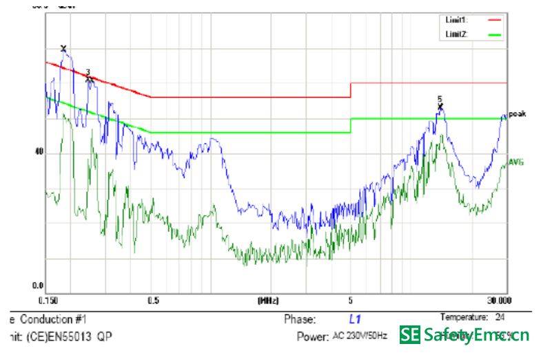
Common-mode interference: Common-mode interference is caused by the parasitic capacitance between the earth and the equipment cable. High-frequency interference noise will pass through this parasitic capacitance, causing common-mode currents between the earth and the cable, which will cause common-mode interference. The following figure shows the conducted FALL data caused by differential mode interference. The front end of the test data exceeds the standard and is caused by differential mode interference:
The following figure shows the EMI principle of the switching power supply:
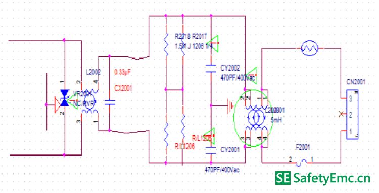
In the picture, the CX2001 is a safety film capacitor (when the capacitor is broken down or damaged, it appears as an open circuit). It crosses between the L line and the N line. When the current between the LN flows through the load, the high frequency noise will occur. The wave is in the loop. The function of the X capacitor is to form a loop between the load and the X capacitor, so that the high-frequency shunt will be consumed in the circuit, and will not enter the mains, that is, through the short-circuit AC of the capacitor, the circuit will not interfere. To the outside. Countermeasures for differential mode interference: 1. Increase the capacitance of X capacitors; 2. Increase the inductance of common mode inductors and use their leakage inductance to suppress differential mode noise (since common mode inductors are used in several winding methods; Wound around or double-wound separately, no matter what type of winding, due to the difference of winding, length of wire, etc., there is bound to be a magnetic leakage phenomenon, that is, the magnetic flux generated by one coil cannot pass through the other coil completely, which makes the LN line. There is an induced electromotive force, which is equivalent to connecting an inductor in series between LN.) The following figure shows common-mode interference test FALL data:
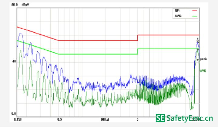
Parasitic capacitance between the power cable and the earth causes the common-mode interference to have a loop. Interference noise flows through this capacitor to the earth, causing a common-mode interference current between the LISN-cable-parasitic capacitance-ground and thus the receiver. Detected, leading to excessive conduction (this can also explain why some motherboard conduction test, not through the ground, a clamp on the ground exceeds the standard. USB mode is not grounded, the current loop can only pass L-diode - load - hot - Diode-N, common-mode current cannot return to LISN, LISN detects less noise, and when the cold plate of the motherboard is directly connected to the earth, there is a loop between the cable and the earth. If common-mode noise is not present at this time If it is absorbed by the front-end LC filter circuit, it will lead to excessive conduction.) Corrective measures against common-mode interference: 1. Increase the inductance of the common-mode inductor; 2. Adjust the L-GND, LC filter on the N-GND, filter out Common-mode noise; 3. Motherboard should be grounded as much as possible to reduce the impedance to ground, thus reducing the parasitic capacitance of the cable and the earth.
Some client may feel that 10th Laptop is little old, so prefer 11th Laptop or 12th laptop. However, you will the 10th cpu is even more powerful than 11th, but price is nearly no difference, especially you take in lot, like 1000pcs. As a professional manufacturing store, you can see Laptop i3 10th generation 8gb ram,i5 laptop 10th generation, intel i7 10th gen laptop, etc. It`s a really tough job selecting a right one on the too many choices. Here are some tips, hope help you do that easier. Firstly, ask yourself what jobs you mainly need this Gaming Laptop to do. Secondly, what special features you care more? Like fingerprint, backlight keyboard, webcam rj45, bigger battery, large screen, video graphics, etc. Finally, ask the budget you plan to buy gaming laptop. Thus you will get the idea which laptop is right one for you.
Except integrated laptop, also have graphic laptop with 2gb or 4gb video graphic, so you can feel freely to contact us anytime and share your basic requirements, like size, cpu, ram, rom, video graphics, quantity,etc. More detailed value information provided in 1-2 working days for you.
10th Laptop,Laptop I3 10th Generation 8gb Ram,I5 Laptop 10th Generation,10th Generation Laptop,Intel I7 10th Gen Laptop
Henan Shuyi Electronics Co., Ltd. , https://www.shuyielectronictech.com