Here is how to use PlanAhead for RTL code development and analysis. Need to explain, all the examples used in this chapter can be found in the installation directory of PlanAhead E:\Xilinx\11.1\PlanAheadestcases\PlanAhead_Tutorial. This section uses the files in the source folder.
First, create a project1. Open PlanAhead. Click the PlanAhead icon on the desktop, as shown in Figure 10-2, to open the PlanAhead software.
2. At the PlanAhead start interface, you can perform a variety of operations: creating a new project, opening an existing project, or browsing related documents.
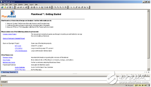
Figure 10-3 PlanAhead start interface
3. Click [Create a New Project] in Figure 10-3, and click the [Next] button in the pop-up window. The new project window shown in Figure 10-4 appears. Enter the project name and path in this window. Click [Next] and the window shown in Figure 10-5 appears.
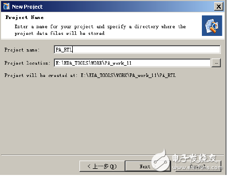
Figure 10-4 New Project Settings Window
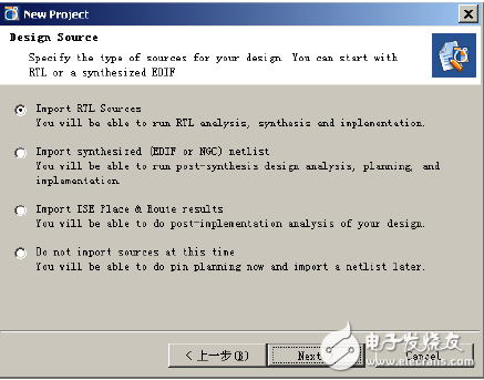
Figure 10-5 Project Type Selection Settings Window
4. Figure 10-5 shows the Select Project Type Settings window. There are 4 options, which are described as follows:
[Import RTL Sources]: Import RTL source code into the project, which can be RTL analysis, synthesis and place and route.
[Import synthesized (EDIF or NGC) netlist]: Import the integrated EDIF or NGC file into the project for comprehensive design analysis, planning and layout.
[Import ISE Place & Route results]: Import ISE layout results (XDL, GZ files, or NCD), constraint files (UCF), timing files (TWX), etc., to analyze the implementation results.
[Do not import sources at this TIme]: Create an empty project without importing any files. Select this to perform pin planning and allow you to import netlist files later. Select [Import RTL Sources] and click the [Next] button to enter the dialog box shown in Figure 10-6.
5. In Figure 10-6, click the [Default Part] right navigation button to open the [Select Part] window, select the device shown in the figure, click the [OK] button, click [Next] to open Figure 10. -7 The dialog shown.
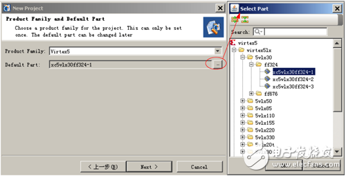
Figure 10-6 Specifying the device
6. In the dialog box shown in Figure 10-7, click [Add Directories...] to specify the source source file directory and select “Import Sources into Project†so that all source files in the directory are added to the project. It is. Click the [Next] button in Figure 10-7 to open the project summary window shown in Figure 10-8.
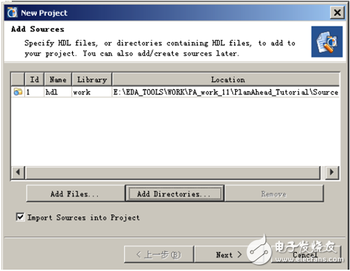
Figure 10-7 Add source file, specify the source file directory
7. In Figure 10-8, click the [Finish] button to complete the creation of the new project.
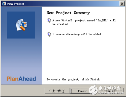
Figure 10-8 Summary of the new project
UPS
True Doulbe-vonversion
microprecessor control optimizes reliability
wide input range
LCD Display 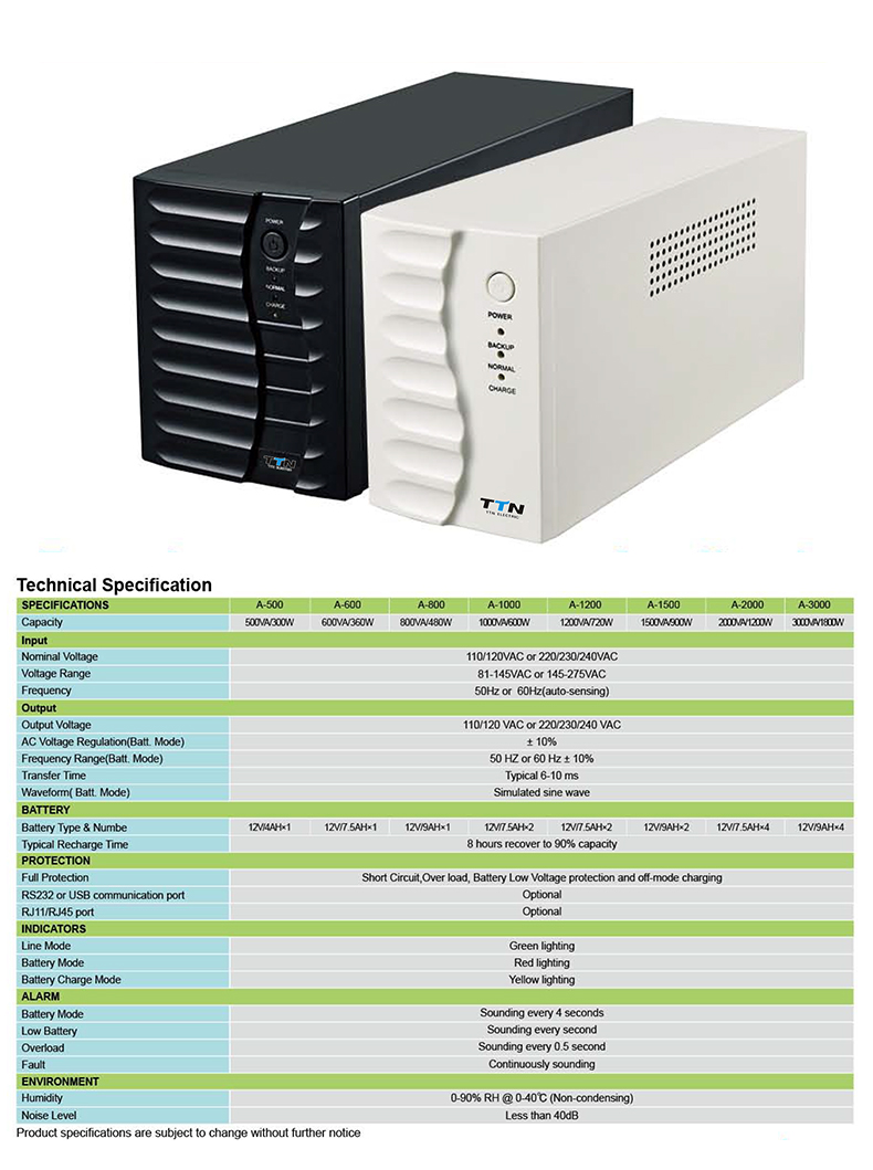
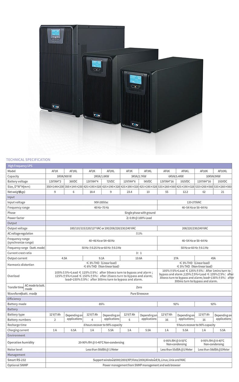
On/Offline Ups,Online Double Conversion Ups,Online And Offline Ups,Online Ups System
zhejiang ttn electric co.,ltd , https://www.ttnpower.com