Keywords: video character overlay, PIC16C73, uPD6453, I2C bus
1 Introduction The video character and time superimposed device is a device that mixes characters or time signals into a video signal to display at the same time as an image signal at a specific position on the screen. This technology is an important field in applied TV technology and plays an important role in the application of TV systems. Judging from the working mode of the video character overlay and the composition of its own circuit, there have been three different implementation schemes so far.
The first scheme is the general medium and small scale integrated circuit implementation scheme. That is, all the small and medium-sized integrated circuits such as logic gates, counters, and shift registers are used to realize time superposition of single-channel character sets.
The second scheme is a multi-channel implementation scheme based on FPGA. That is, on the premise of sharing the font ROM, a CPU and a real-time clock, FPGA is used to integrate several independent scanning circuits that display RAM counts to achieve multi-channel character superposition.
The third scheme is the realization scheme of the main control machine and the display execution machine. ATMEL 8951 single-chip microcomputer can be used as the main control machine, and several AT90S1200 single-chip microcomputers can be used as the display execution machine. The I / O port pins of AT90S1200 can be used to customize a serial communication protocol to realize multi-channel character superposition.
Among them, the first scheme is only suitable for single-channel design. With the development of special chips and single-chip technology, this scheme will be gradually eliminated. The principle of the second scheme is similar to that of the first scheme. The use of programmable logic devices simplifies the circuit a lot, but the cost of this scheme is higher. The third solution uses software to realize the function of a hardware scanning circuit, which is more flexible and has a lower cost, but is only suitable for occasions where relatively few characters are displayed. If there are many characters displayed, the software is too complicated and it is difficult to ensure continuous display.
In recent years, the widespread application of video surveillance systems has continuously expanded its capacity. Therefore, its display editing functions, reliability, and the scale and complexity of circuits have also become a problem that designers have paid close attention to. In order to ensure low-cost, high-performance character overlay in the case of a large system capacity, the article attempts to use a highly integrated character overlay system, which uses the microcontroller PIC16C73 introduced by Microchip and the special character overlay launched by NEC Chip uPD6453.
2 New Chinese Character Superposition System The Chinese character superposition system in the article is a four-channel simultaneous sampling character superposition system. It uses a PIC16C73 microprocessor and four uPD6453 chips to superimpose characters on four analog video input signals, and then A mixed signal of four-way characters and video signals is generated and output to the terminal device. The basic working principle is as follows: First, the line and field synchronization signals in the externally input video signal are separated by the synchronization signal separation module. The separation signal is introduced into uPD6453, and the PIC16C73 sends control commands to uPD6453, such as display control, character RAM write address Control, etc., for the four-way uPD6453 loop operation, according to the system function needs to generate the corresponding characters, superimposed with the external input video signal to obtain a mixed signal output to the terminal device for display.
2. A hardware circuit design of the character superposition system Here, PIC16C73 and uPD6453 are used to superimpose Chinese characters, and the block diagram of its hardware structure is shown in Figure 1.
The hardware structure consists of the following 8 parts:
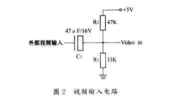
2.1.1 Video input circuit Since the baseline of the external video input signal is about 0V, to superimpose with the character signal generated by the uPD6453 chip, the baseline value must be raised to about 2V. Its design circuit is shown in Figure 2. The circuit output signal Video in is compared with the external video input signal, but the baseline is different, and the waveform shape of the two is completely the same.


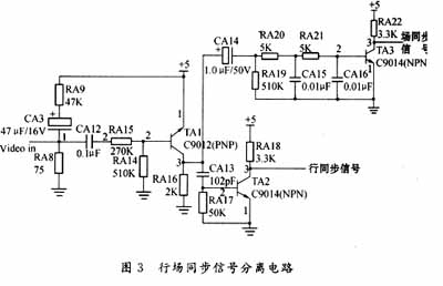
2.1.2 Line and field synchronization separation module, also known as video synchronization signal extraction circuit. Now there are many special integrated circuits on the market that can separate line and field synchronization signals, such as LM1881, but the cost is higher. The article uses discrete analog components to design the circuit, the performance is very stable and reliable, while greatly reducing costs, its design circuit shown in Figure 3.
2.1.3 Character generation module As shown in Figure 1, the CS terminals of four uPD6453 chips are respectively connected to RB0, RB1, RB2, RB3 of PIC16C73; the BUSY ports of four uPD6453 chips are shared and connected to the RC1 port of PIC16C73 ; The CLK ports of four uPD6453 chips are shared and connected with the RC3 port of PIC16C73; the DATA ports of four uPD6453 chips are shared and connected with the RC5 port of PIC16C73. The microprocessor PIC16C73 performs various control command operations on uPD6453, and the generated characters include Chinese characters, letters and numbers. For details about the port functions of PIC16C73 and uPD6453's control commands and control timing, please refer to the NEC data sheet, which will not be described here. It should be noted here that the character size displayed by uPD6453 sometimes does not meet the requirements. We noticed that the external inductance and capacitance oscillation circuit of uPD6453 has a great influence on the horizontal length of the displayed character, but the chip manual does not give specific parameter values. After repeated experiments, we believe that the inductance is 15μH and the capacitance is 56pF. If the inductance value is slightly adjusted, the horizontal size of the displayed characters can be changed, and it can be selected according to your needs when used.
2.1.4 Clock module A clock chip R4543 is added to this design. The chip uses a built-in crystal oscillator, and the accuracy is higher than the general clock chip. The connection between R4543 and CPU is shown in Figure 1. The signal terminals CS, WR, DATA, and CLK of R4543 are connected to RB4, RB5, RB6, and RB7 of PIC16C73 respectively. For the read and write timing of clock chip R4543, please refer to its user manual No more telling. The microprocessor PIC16C73 can read and write to the R4543, and superimpose the current time on the video image signal by uPD6453 to adjust the current time.
2.1.5 Chinese character library module Because the fonts solidified in uPD6453 are mainly Japanese characters, there are no Chinese characters needed. However, it has 16 empty RAM areas, which can be filled in by the user at will (see NEC's data manual for details). Therefore, the system needs a font chip that can store Chinese character dot matrix, and its capacity depends on the range of Chinese characters displayed by the system. The article uses AT24C16 produced by ATMEL as the font chip. The chip capacity is 2Kbyte, which is used to store 12 × 12 dot matrix font data. The data access method of AT24C16 is I2C serial mode. As shown in Figure 1, the SCL and SDA ports of the AT24C16 are connected to the I2C function ports RC3 (SCL) and RC4 (SDA) of the PIC16C73, respectively, and an external 10 kΩ pull-up resistor can be used to implement I2C serial read and write operations. The PIC16C73 reads the Chinese dot matrix data in the font chip through the I2C bus, and then writes it into the uPD6453 on-chip RAM area. For details about the I2C bus read and write timing, see Reference 2.
2.1.6 Serial communication module As shown in Figure 1, the RX (RC6) and TX (RC7) ends of the microprocessor PIC16C73 are connected to the ROUT and TIN ports of MAX202. PIC16C73 has a perfect serial communication interface SCI, using the two pins RX and TX as the two-wire serial communication interface of the communication line, which can be defined as a full-duplex asynchronous mode. Then through an external MAX202 chip to convert the TTL level to the RS232 standard level, it can realize long-distance transmission and communication with the host computer. The host computer downloads the 12 × 12 Chinese character dot matrix data and the current time data, which can update the AT24C16 font matrix data and download the current time data, which is compared with the clock chip time to adjust the time.
2.1.7 Character and video signal superposition circuit This module mainly realizes the superposition of character signal and video signal through 74HC4053 chip. The circuit is shown in Figure 1. The video input signal Video in and the character signal are respectively connected to the two channels of 74HC4053. The switching signal is the output signal VCB generated by uPD6453, which is connected to the channel switching end of 74HC4053. Its working principle is: through the method of switching channels, when characters are to be displayed, switch to the character signal channel, and the rest can pass the Video in channel. The output signal Video out generated by 74HC4053 is the superimposed signal of video signal and character signal.
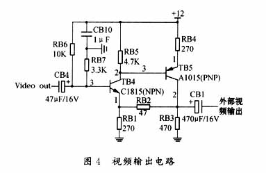
2.1.8 Video output circuit In Figure 1, the character and video mixed signal Video out output by 74HC4053 cannot be directly output to an external terminal device, and it must be processed to restore the mixed signal with a baseline of about 2V to a baseline of about 0V Video output signal. Figure 4 shows the design of a video output circuit.
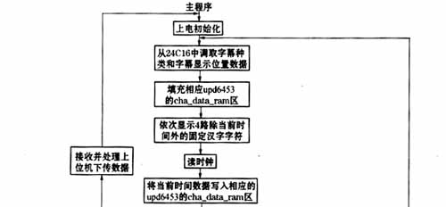
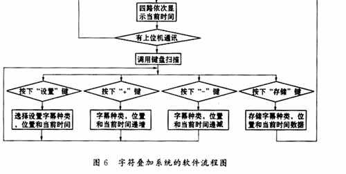
2.2 Software design of the character overlay system Generally speaking, it is necessary to superimpose the title and time information on the video image signal, so that the image signal of the video archive can be distinguished and searched in the future. This is the function that the character overlay system should complete. At the same time, in order that the superimposed character information does not affect the normal image display, the display position of the character should also be adjustable. Based on these two points, the software design of the entire system is divided into 6 states. Show.
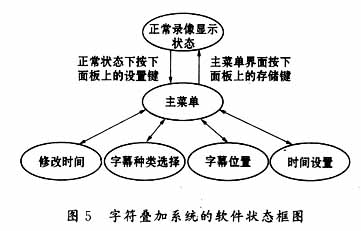
2.2.1 Modification time This setting has two states: "modified" and "not modified". If it is in the "modified" state, the system time will be updated after pressing the store key, otherwise, the system time will remain unchanged.
2.2.2 Type selection of subtitles Through this setting, you can switch the type of subtitle display, for example, display year, month, day, implied year, month, and day, display current time, implied current time, etc.
2.2.3 Subtitle position By setting the row and column position of the subtitle display, characters can be displayed at any position on the screen.
2.2.4 Time setting By setting the year, month, day, hour, minute, and second, the set time can be written into the clock chip R4543 and the modified current time is displayed.
The software flow chart of the system is shown in Figure 6.
3 Conclusion This article's four-way Chinese character superposition system is a supporting product of the surveillance video equipment developed by the author for Tianjin Information Port Jiazi Technology Co., Ltd. and has been successfully applied. In practice, it has been proved that when using PIC16C73 and uPD6453 to design a video Chinese character overlay system, compared with the traditional character overlay system, it has many display characters, strong display editing function, simplified hardware circuit, simple software design, strong reliability, and practical It has the advantages of good sex and moderate price, and it is a better choice for Chinese character superposition in video.
2 He Limin. I2C bus application system design. Beijing: Beijing University of Aeronautics and Astronautics Press, 1995
110V-220V Timed Dimming Switch Line
110V-220V Timed Dimming Switch Line,Switch Control Power Cable,Extension Cord On Off Switch,Light Socket Extension Cord
ShenZhen Puchen Electronics Co., Ltd. , https://www.szpuchen.com