Automotive CAN network test development method
I. Introduction
With the development of automotive electronic technology and the improvement of automotive performance requirements, the number of electronic control units (ECU, Electronic Control Unit) on the car is increasing, and the interactive information between each electronic control unit is composed of CAN, LIN, MOST bus Network. Therefore, the development of the vehicle network is particularly necessary. The development process of the current vehicle network is generally based on the internationally-used V-mode development process.
The V-mode process of vehicle network development includes the following main aspects: network requirements definition, network specification formulation, and network test verification. After the definition of the current network requirements and the formulation of the network specifications are completed, it will enter the later stage of network design and test verification. The network test verification phase is mainly to perform network test verification on the samples or products that have been designed to ensure the function of the samples or products Consistent with the previous needs.
The network test verification phase is mainly engaged in network test demand analysis, network test specification formulation, network test system development and network test implementation, and analysis of problems that occur during the test process.
2. CAN network test development process
The vehicle CAN network test development process mainly includes the following aspects: test plan formulation, specification formulation, automated test system development, test implementation, and test report summary.
The test plan formulation mainly considers the resource requirements (tool requirements, manpower requirements, etc.), task division, and time requirements required for network testing to ensure that subsequent work can be carried out smoothly and effectively.
The formulation of the test specification is mainly to determine the content of the network to be tested. Throughout the network development process, the network test specification should be carried out after the network requirements specification is completed. The purpose of the network test is to confirm whether the ECU products provided by the supplier meet the requirements of the network requirements specification. Because of this, the formulation of CAN network test specifications must be based on CAN network requirements specifications. The test specification needs to include all test items and descriptions of the test environment requirements, test steps, and test tool requirements required for each test item.
Test system development includes software system development, hardware system development, and software and hardware system integration. Software system development mainly includes:
The division of software architecture;
Test program development based on test content;
Library file development based on network communication messages;
Test panel development used to control test execution and other aspects;
Development of related control programs used to control different test systems to make them work effectively.
Hardware system development mainly includes:
Network test auxiliary controller development;
Selection of test tools (such as program-controlled power supply, CAN network communication equipment, CAN network interference equipment, CAN network waveform acquisition equipment, etc.).
The purpose of software and hardware system integration is to debug the software development system and the hardware development system to make it seamlessly integrated and work effectively.
Test implementation is the specific implementation link of CAN network test, mainly including:
Construction of test environment (building of test bench, etc.);
Execution of the network test of the ECU under test;
Record test results and save test records.
The test report summary mainly analyzes the ECU under test based on the test results to determine whether the ECU under test meets the requirements of the CAN network requirements specification.
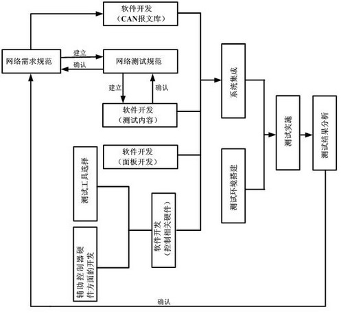
Figure 1 CAN network test flow chart III. CAN network test development tool
CAN network test development requires the following main development tools: DOORS, Visual C ++, Matlab / Simulink, CANoe.Matlab Interface, CANoe, CANdela, CANoe.DiVa, CANcard, CANdb ++, CANscope, CANstress, Code Warrior, Protel, etc.
DOORS is a requirements management tool that can be used to organize network test content and provide input for test requirements for subsequent development tools. Visual C ++ is mainly used to develop control programs for coordinated work between hardware systems and control programs for human-computer interactive operation interface. Matlab / Simulink and CANoe.Matlab Interface are mainly used for modeling the test content based on the model and used to realize the automatic generation of test code. CANoe is a network simulation and testing tool. It develops test programs related to network communication under CANoe and uses CANoe to generate network test reports. CANscope is used for the measurement and analysis of the physical characteristics of CAN signals. It has a variety of sampling trigger methods and is used to collect the waveform of the ECU under test in the network automatic test system. CANstress is used to interfere with CAN network communication to test the fault tolerance of ECU and network systems. It is used to interfere with the network under test in the network automation test system. CANdela is used to edit the diagnostic database based on KWP2000 and UDS. For the test program, the input file is a library file edited by CANdela, the output file is a test program related to CANoe diagnosis, and CANdb ++ is used to edit the database of CAN communication messages.
Fourth, the realization of a CAN network automated test system
According to the test procedure introduced in Section II, a CAN network automation test system is developed using the corresponding development tools introduced in Section III. The functions of the CAN automated test system include: control of the test process, automatic execution of test cases, data collection and processing, and automatic generation of test reports.
1) Formulation of test specifications: using DOORS demand management tools, according to network requirements specifications and diagnostic requirements specifications, CAN network unit test specifications, system test specifications and diagnostic test specifications are formulated;
2) Use CANdb ++ for software development of CAN message database, and CANdela for diagnosis database development;
3) According to the network unit test specification and system test specification formulated in 1), use Matlab / Simulink and CANoe.Matlab Interface to generate the corresponding test program, and integrate in the CANoe environment;
4) According to the completed diagnostic database of 2), use CANoe.DiVa to generate diagnostic test program and integrate in CANoe environment;
5) Use CANoe, Matlab / Simulink and Visual C ++ for software development of the control panel;
6) According to the test requirements of the test specification, use Visual C ++, Code Warrior and Protel to develop network auxiliary controllers and other hardware and software such as fault implantation;
7) Use Visual C ++ to develop control programs for test tools such as CANstress, CANscope and programmable power supply;
8) Use Visual C ++ for system integration.
The network automation test system architecture and schematic diagram are shown in Figure 2 and Figure 3.
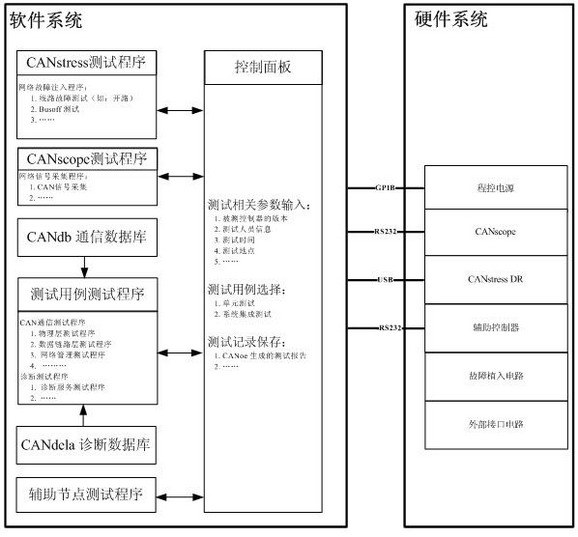
Figure 2 CAN network automatic test system
Figure 3 Schematic diagram of CAN network automated test system V. Conclusion
This article first introduces the CAN network test process in detail; second, it introduces the development tools needed for CAN network test development and introduces the specific functions of these development tools; finally, based on the process and using these development tools, the development is described in detail Details of the development of automated test systems in the process.
The JUK universal Screw Terminal Block series has the typical features which are decisive for practical applications:
l The universal foot allows the terminal blocks to be easily snapped onto the NS35 or NS32 DIN Rail with G shape.
l Closed screw guide holes ensure screwdriver operation perfect.
l For terminal block with different wire cross-sectional areas, complete accessories are available, such as end plates, partition plates, etc.
l Potential distribution achieved by fixed bridges in the terminal center or insertion bridges in the clamping space.
l Same shape and pitch Grounding Terminal Blocks as the JUK universal series.
l Adopt ZB marker strip system,achieve unified identification.
Din Rail Fuse Terminal Block,Screw Fuse Terminal Block,Din Rail Fuse Holder Terminals,Din Rail Fuse Terminal
Wonke Electric CO.,Ltd. , https://www.wkdq-electric.com