System Overview
This article refers to the address: http://
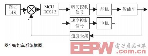
The smart car system is mainly composed of function modules such as path recognition, speed acquisition, steering control and vehicle speed control. The path recognition function adopts a CMOS camera, and the analog video signal is video-decoded, and then binarized and converted into image data of 18×90 pix and then sent to the MCU for processing; the steering control is adjusted based on the fuzzy control algorithm; The vehicle speed control adopts the classic PID algorithm, and sets different given speeds by judging the different shapes of the track. The system achieves closed-loop control of the entire system by continuously collecting real-time road condition information and speed at a frequency of 50 Hz, as shown in Figure 1.
Intelligent car image acquisition and storage
Image acquisition module design
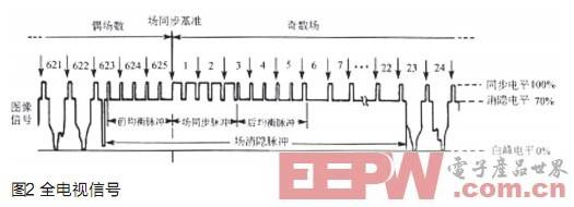
After the CMOS camera is powered normally, the signal waveform of the original image can be output. It is an analog signal of the PAL system, and includes signals such as line synchronization, line blanking, field synchronization, and field blanking as shown in FIG. 2 . However, the signal of this form cannot be directly used by the CPU. It needs to be added to a video decoding chip such as SAA7111. Its function is to convert the analog signal output by the camera into a digital signal, and simultaneously generate various synchronization signals, and the CPU uses the synchronization signal to image the image. The digital signal is stored in an external FIFO chip AL422, which constitutes the basic path detection module, as shown in Figure 3.

Image data storage
The SAA7111 is an enhanced video input processor chip from Philips that is commonly used in highly integrated circuits for embedded video applications. During operation, the analog video image is input from one of the four input ports of the SAA7111. After analog processing, one channel is output from the analog output for monitoring through the buffer, and the other is digital chrominance signal after A/D. The luminance signal is separately processed for luminance signal processing and chrominance signal processing. The result of the luminance signal processing is sent to the chrominance signal processor for comprehensive processing to generate Y, U, V signals, which are outputted from the VPO after formatting, and the output signal format is 422YUV or CCIR-656 (8 bits); The other way enters the synchronous splitter, and through the digital PLL, generates corresponding lines, field sync signals HS, VS and pixel clock signals LLC and LLC2, which are the basis for realizing video data acquisition. The image size of each frame output by SAA7111 can be set to 720×286, and the data amount is relatively large compared with the processing speed of the single-chip microcomputer. The ideal image size is 18×45, and the compressed data volume is only the original image. 0.394%. In order to effectively compress the image data, the digital signal of the image can be stored in the FIFO, and the image size can be compressed after a certain frequency division process. The FIFO chip used by the system is AL422B.
In order to realize the frequency division processing of the image digital signal, it can be divided into two implementation modes, one is software frequency division, and the other is hardware frequency division. For the software crossover, the system does not need an additional frequency dividing circuit, but the microcontroller uses the control signal output by the decoding chip SAA7111 to divide the read clock and then perform the actual read operation. The disadvantage of this method is frequency division. The work needs to occupy the single-chip resources, affecting the real-time performance of the system; for the hardware crossover, it is necessary to add a special frequency-dividing processing circuit to achieve image compression without the need of single-chip control, thereby fundamentally reducing the single-chip microcomputer. The amount of data processed and the time it takes to read the image. Therefore, the system adopts the hardware frequency division method. The frequency division mode of the specific signal is shown in Figure 4. CREF represents the pixel clock. After dividing, the write clock WCK of AL422B is obtained. HREF represents the line reference signal, which is obtained after frequency division. The signal acts as a write enable signal for AL422B.
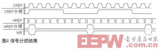
Image denoising and feature extraction
Binary image
Image binarization is a basic technique in digital image processing technology. In this system, since the track is composed of two colors of black and white, and the background color is basically white, the task of the system is to recognize the black lead. The position of the running line, because the interference of its image is not very strong, the binarization technique can be used as the image preprocessing of the system. After binarization, the original white pixels are represented by 0, and the black pixels are represented by 1. The key to image binarization technology is how to select the threshold. Generally speaking, commonly used methods include global threshold method, local threshold method and dynamic threshold method. Since the light on the track is relatively uniform and the background color around the track is basically white, the global threshold method is adopted in the system design, which can achieve the advantages of simple algorithm and high execution efficiency.
Binarization threshold selection
In the analysis of the track environment, we can find that the brightness of the black line part is relatively fixed, the range of fluctuation is very small, less than 20 (the maximum brightness value is 255), and the brightness value of the white bottom plate changes relatively. Some, but still can guarantee a large gradient with the brightness value of the black line. Therefore, the histogram statistical method can be used to automatically set the threshold thereof, as follows.
First, all the data of an original image is stored, and then the first pixel of the whole image is counted, and finally the number of pixels corresponding to the first brightness value is counted, and a double-wave peak image appears as shown in the figure. 5 is shown. This will allow a more direct comparison of the region of the luminance value set, with the midpoint value at the center of the two peaks as the binarization threshold for the track. The algorithm has a high precision and can find an ideal threshold. Although it takes a long time to execute, it is only an initialization operation before the car starts to run, and it has no effect on the speed of the car after the start. The plan is available.
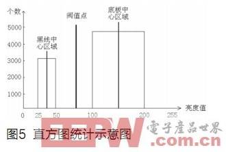
Image Denoising
During the movement of the car body, the image does not appear too much noise after binarization, but a small part of the salt and pepper noise appears locally. The typical image is shown in Figure 6. In this system design, the purpose of image processing is to accurately find the center position of the black line. Since the area of ​​the noise in the image is very small, and generally appears far away from the black line, there are many methods of processing, and the central coordinate recursive method can be used.

Since the black line of the track is subdivided into the coordinates of each line, the difference between the central coordinate values ​​between the adjacent two lines is relatively small, and the difference is generally not more than 5 after experimental testing. Push. Therefore, the center coordinate of the previous line can be used to recursively to solve the problem. The specific steps are as follows.
(1) Since the black line near the camera has a good shooting effect, not only the width of the black line is relatively large, but also basically no noise occurs, and it is a very good choice to use it as a reference point for recursion. Since this is the reference point of the whole image, the accuracy is relatively high. When calculating the center coordinate value of the first line, the black line continuous counting method is used, that is, only three or more "1"s are continuously read. Only valid black lines are counted, and the number of black lines is recorded. Otherwise, clear it, and finally check whether the number of black lines in the line is 1. If not 1, use the second line of image data for judgment. So increment until you find a unique black line.
(2) Searching for the black line position in the interval of 10 points on the left and right sides of the left and right sides based on the center coordinate found for the first time, and then using the center of gravity method to find the center of the black point in the interval. The coordinate value and use it as the center coordinate reference point for this line.
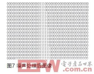
(3) Step by step to the previous line according to step (2). If a line with all 0s is encountered, the search for the black line is stopped. The image obtained by the algorithm shown in Fig. 6 is processed as shown in Fig. 7. It can be seen that this method can effectively eliminate the noise of the image.
CNC Machining Service, Medical Parts CNC Machining Service, High Precision Parts CNC Machining Service
ShenZhen Haofa Metal Precision Parts Technology Co., Ltd. , https://www.haofametal.com