It can sometimes be used in instrumentation amplifiers. The circuit requires only one operational amplifier, as shown in Figure 1. It is convenient to use it where there are no harsh requirements for high input impedance or gain.
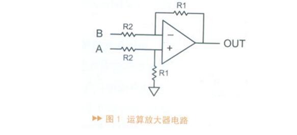
The circuit's transfer function is:

The advantage of the differential amplifier is its simple structure. The main drawback is its low input impedance. Since the gain is determined by R1/R2, there is a trade-off between high gain and high input impedance. In addition, reducing the signal voltage and then amplifying it (as the phase path) is not a method to obtain good noise performance. For the inverting path, additional resistors are added and the noise gain of the inverting amplifying circuit is always higher than the signal gain. Increasing the input impedance requires increasing the value of the resistor, which will produce more noise. Finally, the common mode rejection ratio is also limited. To improve these shortcomings, the first step is to buffer the input so that the input impedance problem is solved, as shown in Figure 2.
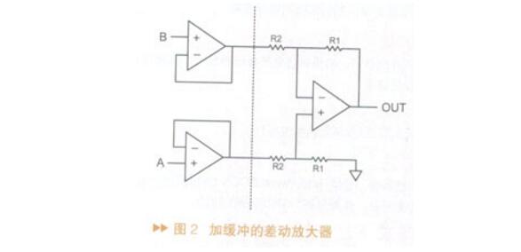
While buffering the input, if you introduce some gain, in addition to high impedance, it will also produce very good noise performance, as shown in Figure 3.
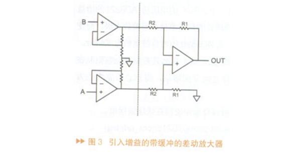
The noise of the differential amplifier in the circuit still exists, but the noise is divided by the gain of the first stage when converted to the input. Since a very small resistor can be used, the first stage noise can be made very low without affecting the input impedance. Another advantage of this structure is the wider bandwidth at high gain. The reason is that the voltage feedback amplifier has a certain gain-bandwidth product. By distributing the gain to the two-stage amplifier, the gain of each stage can be made lower, and the gain of the differential amplifier stage can be reduced, so that it is not limited by the gain-bandwidth product. However, one unsolved problem is the common mode rejection ratio. The circuit in Figure 3 amplifies both the common-mode signal and the differential signal, and all common-mode rejections are implemented in the differential amplification stage, so it is easy to exceed the input voltage range of the first stage.
Three Op Amp Instrumentation AmplifierThe grounding point in the first-stage amplifier circuit in FIG. 3 is removed to solve the problem of common-mode rejection, thereby forming a three-op-amp architecture instrumentation amplifier, as shown in FIG. 4 .
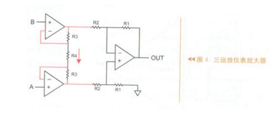
The first-stage circuit allows the common-mode signal to pass through without any amplification or attenuation, and the second-stage differential amplifier removes the common-mode signal. Since the differential gain is additionally increased, although the matching condition of the resistor is not improved, the effective common-mode rejection capability of the system is enhanced. In practical applications need to pay attention:
1) must provide gain in the first level;
2) The common-mode rejection of the system is not determined by the common-mode rejection ratio performance of the first two amplifiers, but depends on the degree of matching of the two common-mode rejections. However, dual op amps never give this indicator, so the CMRR performance indicator must be required to be at least 6 dB better than the desired target performance indicator when selecting;
3) If the resistor has some leakage path to ground, the CMRR indicator will decrease;
4) The components in front of the instrumentation amplifier must be designed as balanced as possible. If the low-pass filter in the in-phase path of the instrumentation amplifier and the low-pass filter in the inverting path have different cutoff frequencies, the CMRR characteristic of the system will decrease as the frequency increases.
For the first stage of the instrumentation amplifier, each op amp must maintain the same voltage across its two voltage inputs. The differential voltage across R4 in Figure 4 should be the same as the voltage at both inputs. This voltage produces a current that flows through resistor R3 and produces the gain of the amplifier.
Three op amp instrumentation amplifiers usually encounter the following problems:
1) This structure amplifies the differential signal and then removes the common-mode signal. The intermediate node between the two stages of the circuit carries approximately half of the differential signal plus the common mode signal. Make sure that this signal is within the operating range of the op amp. When changing the common-mode component of the input voltage, if you see a phenomenon similar to saturation, you should check this first.
2) The current flowing through R4. When the gain of the instrumentation amplifier is set high, R4 will be small, which means that when the differential voltage is high, the current generated by R4 will be quite large. It is necessary to check whether this situation has a negative effect on the system.
3) Capacitance in the feedback path. The traces of the feedback path should be as short as possible, and excessive capacitance of the feedback path can degrade the common-mode rejection ratio performance at high frequencies.
Two op amp instrumentation amplifiersIf you do not need the high performance of a three-op-amp structure, you can use two op-amp structures for simplicity. The main advantage of this structure is its simple structure, which requires only two op amps and four resistors, as shown in Figure 5. Since there are few devices that contain three op amps, a three op amp structure usually requires a four op amp device. The extra one op amp needs to consume more power, so the two op amp structures will also have lower energy consumption. In addition, as with the three op amp structures, the two op amp structure circuits also have high input impedance. However, the performance of the two op amp instrumentation amplifiers is worse. Through calculation and analysis, the common mode rejection ratio of this structure is slightly higher than that of the differential amplifier structure. In the worst case, the CMRR for 0.1% resistor matching is not 54 dB but 50.5 dB. Unlike a three-op-amp instrumentation amplifier, this CMRR value does not improve with gain. Because the two paths are unbalanced, the frequency response of the in-phase path signal is different from that of the inverting path signal. Since the inverting path passes through two stages instead of the first stage, a phase delay occurs in the inverting path, and the slew rate and bandwidth characteristics are also different, and the noise performance is also poor.
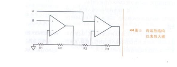
The common problems with two op amp instrumentation amplifiers are:
1) Since the output voltage of the first stage is the amplified input voltage, which includes the common-mode voltage, it is necessary to pay attention to the output voltage of the first stage;
2) Because the CMRR of the two op amp instrumentation amplifiers is extremely sensitive to the matching condition of the resistors, it is necessary to pay attention to the matching of the resistors;
3) High frequency performance. Therefore, for these three structures: the difference amplifier is very good and simple, requiring only one op amp and four resistors. However, its input impedance is related to the value of the selected resistor, and the performance of noise and CMRR is also poor.
2) The three-op-amp instrumentation amplifier's first-stage circuit provides high input impedance. When we introduce gain in the first stage of the circuit, it also improves noise and CMRR performance.
The two op amp structure instrumentation amplifier has a much simpler circuit structure than the three op amp structure and also has a good input impedance characteristic. However, its noise and CMRR performance cannot be improved with increasing gain.
Common instrumentation amplifier modelsAt present, there are many models of instrumentation amplifiers. It is AD's only, AD620, AD621, AD622, AD623, AD624, AD625 are all, there are probably dozens of other. There are also many TI companies, such as INA128, INA129, INA333, etc. There are 44 kinds. These are dedicated integrated instrumentation amplifiers, and can also be built directly from an instrumentation amplifier circuit using ordinary precision op amps.
Instrumentation Amplifier Magnification FormulaInstrumentation amplifier magnification formula derived as shown below
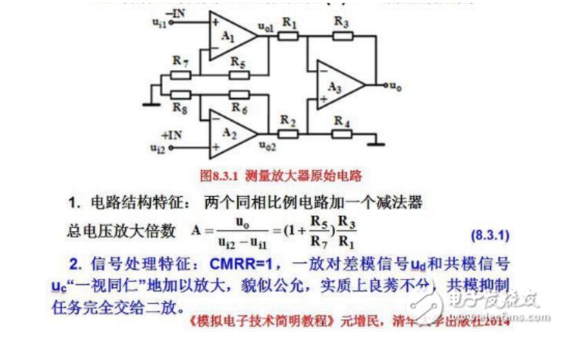
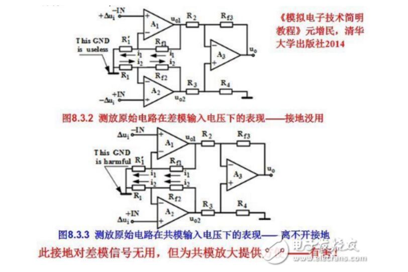
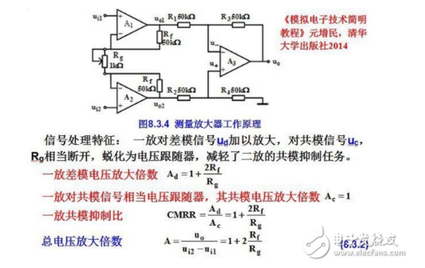
Ternary polymer lithium battery refers to a lithium battery whose positive electrode material uses a ternary positive electrode material of lithium nickel cobalt manganese or lithium nickel cobalt aluminate. There are many kinds of positive electrode materials for lithium ion batteries, mainly lithium cobalt oxide, lithium manganate, Lithium nickelate, ternary materials, lithium iron phosphate, etc. At present, the lithium battery of ternary material has replaced the lithium cobalt oxide battery that was widely used before, and is widely used in the field of notebook batteries.
Ternary Battery Board,ISO9001 Certificated,RoHs Certificated PCB,UL Certificated,Ternary Battery Protection Board
Huizhou Liandajin Electronic Co., Ltd , https://www.ldjpcb.com