Foreword: "4G is coming, is 2G and 3G still useful?" This is a problem that many end users often ask. In fact, we can look at this issue like this. The first is voice service. Many times, our mobile phone is used for voice calls, and our 2G network is usually used. Second, in the period of rapid development of mobile communications, data services have shown a blowout phenomenon. People born in the 1960s and 2000s have increasingly enjoyed the convenience and quality of life improvements that data services bring to them. Forecasts show that by 2016, mobile terminal users will use video more than 6 times in 2011, and online mobile games will increase nearly 10 times.
This brings up a problem - smaller and smaller capacity space is facing more and more users, which is a very serious problem faced by every operator in the world today. Generally speaking, operators have to increase their capacity by two means. One is to increase the carrier frequency carrier fan, and the other is to increase the base station. However, with the development of wireless communication, with the increasing number of users, the density of base stations is getting larger and larger, the configuration of base stations is getting higher and even full load, and network congestion frequently appears. Our expansion of hotspots seems to have a new bottleneck.
In this paper, we will analyze in detail how to use CommScope Andrews dual beam antenna to improve such phenomena in the implementation of wireless network antenna feeder field engineering.
I. Operator's problemThe so-called hot spots are the dense areas where traffic is concentrated. Often, the base station density and the base station configuration are the highest in these areas. In other words, the operators have actually worked hard on the hardware, and the available site resources and carrier frequency resources are exhausted. However, hotspots are often not fixed, or there are many new data or sudden bursts of traffic in hotspots. These points are even more difficult to optimize.
The most prominent phenomenon at present is as follows:
Tidal phenomenon: These areas are divided by time spans, and hotspots appear in large commercial areas, schools, high-density residential areas, business centers, etc.;
Large public spaces: These areas are either high-density traffic or high-density for part of the time. Hot spots are generally stations, theaters, stadiums, etc.;
Incidents: This type is uncontrollable and sometimes manifests as traffic jams, gatherings, etc.
Second, the advantages of dual beam antennaIn the case that conventional means cannot continue to increase capacity, we can try to use another idea to improve the problem, starting from the antenna feeder link.
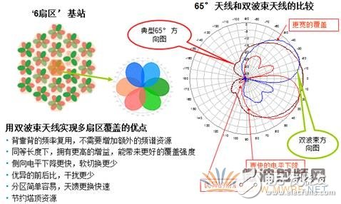
In response to this situation, Comm Andrew introduced the "cell fission" solution, which splits the original three base stations into one single base station and six sectors, and even more. This solution can maximize the utilization of frequency division and sector division to increase the capacity of the base station, so as to alleviate or even solve the congestion phenomenon caused by insufficient capacity in the hot spot area. The research and a large number of practical applications show that in a typical application scenario, the fissile '6 sector' base station can increase voice capacity and data throughput by 30% -100%. The flexible configuration of multi-sector base stations ("3 sectors, through sector splitting of existing networks" also has a wider range of application scenarios and flexibility, without the need to re-plan the existing network.
If the sector fission scheme is simply replaced with a traditional narrow-beam antenna, then it will require a coherent consideration of tower installation space, tower load capacity, wind load capability, and increasingly sensitive site acquisition issues. CommScope Andrew's dual beam antenna is a better choice to avoid these problems.
3. Field engineering application of dual beam antennaFor high-density areas, dual-beam antennas and sector splitting solutions have major advantages:
The installation and commissioning of the dual beam antenna is the same as the conventional one. This is because such special antennas are used in some special areas and are tailor-made. There are some different processes for installation than traditional installations, and the mechanical installation of the antenna itself is no different from the traditional base station antenna. .
The typical field engineering implementation process is:
·Base station site survey
·Custom antenna model and development plan
·Field construction
·Network data collection analysis and post-adjustment optimization
We present a typical example of a dual beam antenna for field applications.
The operator of a certain area found that the SN base station covering a new village has a higher traffic volume of 2 sectors, and the configuration of the sector has reached the 12TRX configuration, and the service absorption problem cannot be solved by continuing to expand. Therefore, it is planned to use the Andrew dual-beam antenna (model HBXX-3817TB1-VTM, the frequency of use is 1800MHz) for cell splitting, to achieve service absorption, and to reduce the double busy cell.
Base station site survey
After on-site investigation, we found that the current sector has high-density residential areas, commercial buildings, large markets and major roads.



(covering the left side of the main lobe) (covering the middle of the main lobe) (covering the right side of the main lobe)
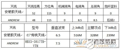
The main information of the base station is as follows:
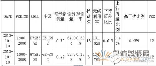
GE/DE-SN2 adjusts the amount of busy traffic before

GE/DE-SN2 adjusts the amount of busy data traffic before
v Original antenna coverage area simulation
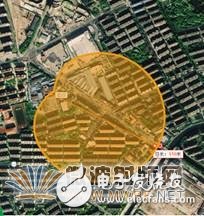
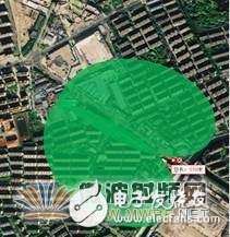
(original antenna coverage simulation) (ANDREW antenna coverage simulation)
Custom antenna models and development options
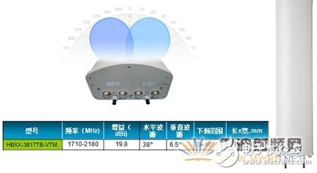
The capacity is improved by splitting the current SN2 cell in the current network. The specific method is as follows:
1: The dual beam antenna is selected by CommScope Andrew's HBXX-3817TB-VTM.
2: The original antenna of this sector is installed on the first platform of the tower (52 meters high). The dual beam antenna will be mounted on the second platform (48 meters high).
3: The base station adds two 2 sectors, which are 4 sectors and 5 sectors respectively. The antenna feeder system connection is adjusted to: connect 4 sectors and 2 feeder links to the original antenna, and 2 sectors and 2 feeder links. To the left two ports of the Comm Andrew dual-beam antenna, the five-sector two feeder links are connected to the right side of the Comm Andrew antenna. That is, the direction covered by the original SN2 cell is covered by the new SN2/4/5 three cells, and each cell is configured as 6TRX, so that the carrier frequency capacity of the entire area is increased from the original 12TRX to 18TRX.
4: In order to maintain the wireless environment of the area covered by Comm's Andrew antenna, the azimuth of the original antenna is adjusted to 80 degrees, text box: The original antenna CommScope Andrew antenna azimuth is set to 120 degrees.
Station number station name LACCI azimuth height total inclination configuration transmission
Original D72E592DE-SN2627258770120488122
Dual beam antenna + single beam antenna D72E594DE-SN46272587728052962
D72E592DE-SN262725877093488.562
D72E595DE-SN562725877314762
Basic situation of the cell before and after DE-SN2 adjustment
Original antenna
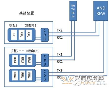
(configuration scheme simulation diagram)

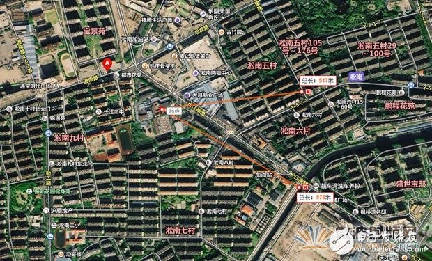
Installation plan covers the simulation
Site construction
A. Perform the third-order intermodulation test of the antenna before installation. The PIM values ​​of the four ports of CommScope Andrew's antenna are better than -150dBc, which meets the operator's installation requirements.
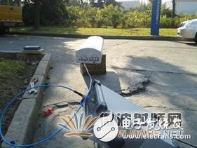
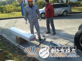
(field test environment)
Antenna left port right port
Left 1 (dBc) Left 2 (dBc) Right 1 (dBc) Right 2 (dBc)
HBXX-3817TB1-VTM-166-161.9-156.8-166.3
B. Electrical performance test of the feeder link to be installed:
Sector link VSWRPIM (dBc) rectified PIM (dBc) antenna
4TRX2-76-90.4 original antenna
4RX2-89
2TRX11.36-98ANDREW
2RX11.21-79-104.6
5TRX31.19-60-94.3
5RX31.19-68-102.9
Before the antenna was installed, the link antenna feed performance test was carried out. Among them, the third-order intermodulation of four feeder links did not reach the mobile use standard (-80dBc). After the fault point location check, they are all indoor main feeder connector nodes. After installing and reinstalling the connector, all six feeder links meet mobile usage standards.
C. Installing the antenna
The four sectors are connected to the antenna of a foreign manufacturer on the first platform, and the second and fifth sectors are connected to the CommScope Andrew dual beam antenna. ANDREW is installed on the second platform, and the waveform and beam coverage are as close as possible to the antenna of a foreign manufacturer. Therefore, the mechanical tilt angle is set to 0 degrees, and the electric tilt angle is set to 8.5 degrees. The antenna of a foreign manufacturer is installed on the first platform. The mechanical inclination is 9 degrees.
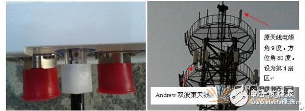
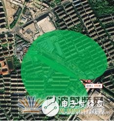
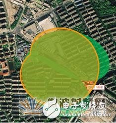
After installation, Andrew's dual-beam antenna coverage simulates the comparison between the Andrew Antenna and the original antenna.
3. Network data collection and analysis stage
A. Coverage test
The road test is performed immediately after the installation is completed. The road test is designed to reflect whether the dual beam antenna can outperform the conventional 65-degree antenna in terms of signal coverage. The road test is performed by the operator network optimization team.
After the first road test, the test team feedback is as follows:
The coverage level of the 1.2 sector is normal and slightly higher than the original antenna coverage level before installation;
2. 5 sector coverage is poor, basically at -78dB, and the call channel cannot be established;
3. The drive test area is equivalent to the original antenna.
DT coverage level statistics
Total sampling points of test time ≥-85dBm≥-75dBm
Ratio sampling point ratio sampling points
1112898.28%1093773.62%8192 before installation
After installing dual beams 1305199.23%1295182.55%10773
DT coverage quality statistics
Test time total sampling points 0 level +1 level + 2 level + 3 level + 4 level 5 level + 6 level + 7 level voice quality
Ratio sampling point ratio sampling point number 0 level +1 level + 2 level + 3 level + 4 level ratio
1026296.37%98893.63%37396.37% before installation
After installing dual beams, 1207697.63%117902.37%28697.63%
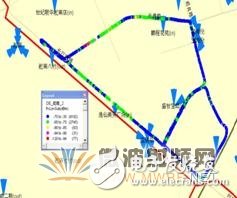
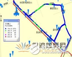
2 sectors of the road test level before installation, statistics of the 2 sectors of the road test level after installation
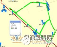
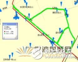
2 sectors of road test quality statistics before installation, 2 sectors of road test quality statistics after installation
B. Background data statistics
The S2 cell mainly covers high-density residential areas, so the traffic volume at the time of busy is the highest traffic volume of the community on the day, so the statistics of the busy hours before and after the test are selected for comparison.
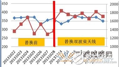
According to the traffic comparison between the busy hours of the week before and after the installation, the traffic volume and data traffic of the cell before the test is significantly increased after the installation of the dual beam antenna. After installation, traffic volume increased by 30% to 17Erl, and data traffic increased by 98% to 149MB. After the 5 sector main coverage area, the switch is normal.
Community name DE-æ·žå—_2
Traffic (Erl) data traffic (MB)
Before installation 55.45152.98
Dual beam antenna after installation 72.06301.81
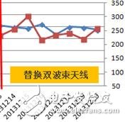
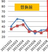
Changes in traffic volume and data traffic before and after S-base station installation of dual-beam antenna
At the same time, the number of dropped calls, the proportion of uplink and downlink quality differences, and the high interference ratio of the S2 cell have also improved to some extent, and other wireless indicators are stable.
A. Regional performance indicators:
Considering that the S2 increases the dual-beam antenna, the coverage increases, which may cause the traffic volume of the neighboring cells to decrease. Therefore, the late busy hour indicators before and after the installation are also selected for comparison. The area taken involves three macro stations, two street stations, as shown in the following figure:
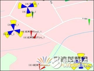
Coverage of surrounding cells of S base station
From the comparison results, from the indicators before and after installation, the overall business volume in the region has increased, the data traffic has increased significantly, and other wireless indicators are normal.
Cell traffic in the cell name area
Traffic (Erl) data traffic (MB)
Before installation 372.391674.86
After installing the dual beam antenna, 381.161845.01
Changes in traffic and data traffic before and after the installation of dual-beam antennas
After the S-cell 2 cell adds a dual-beam antenna, the height is reduced by 4 meters compared with the original, but the radiation range of the dual-beam antenna is basically the same as the original coverage, so as to verify the difference of the coverage effect under the premise that the upper 3dB points are basically the same. Andrew's dual-beam antennas are designed with independent ESC angles for each beam, so you can make pitch angle changes at any time if you want to increase or decrease the depth of coverage.
After comparison tests, the following characteristics of the dual beam antenna were verified:
1. The beam edge level is reduced quickly, effectively reducing unnecessary soft switching;
2. In the performance indicators, there is the effect of increasing the traffic volume in the area, reducing the interference and the proportion of the upper and lower quality differences;
3. It has the advantages of increasing the coverage distance, increasing the depth coverage, and improving the voice quality in the area. It is helpful for areas with suburban areas and high-allocation base stations that have business needs but cannot be expanded.
Dual Beam Antenna Field Engineering Tips:
1. The antenna tilt angle setting is too large or too small, resulting in deviation of the coverage area;
2. The coverage simulation is not performed in advance, resulting in deviation of the beam coverage;
3. In order to carry out comprehensive consideration of the area, it leads to cross-regional or excessive traffic;
4. The problem of the antenna link is not found, resulting in an imbalance between the uplink and downlink.
5. The base station traffic density is too high, and the carrier frequency expansion is still unable to support. It needs to use more beam antennas, such as the Andrew brand's three or five beams or more beam antennas.
USB Slip Rings are an increasingly popular way to provide power and data to rotating devices. By using a slip ring, you can avoid having to run cables through a hole in the device's enclosure, which can be difficult and messy. USB slip rings also provide a convenient way to update firmware or change settings on the device without having to open the enclosure. It is commonly used in applications where there is a need to send or receive data or power between a stationary object and a rotating object, such as in an industrial setting where a machine needs to be powered while it is still in use.
Oubaibo's USB Slip Ring, Rotary Swivel Joint manufacturer, chooses the high-quality Senring slip rings, and fiber Rotary Joint products. The company has been in business for many years and is a leading supplier of quality slip ring products. They offer a wide range of products, including high-quality sending slip rings, fiber rotary joints, and more. Their products are affordable and of the highest quality. They are a great supplier for those looking for quality slip ring products.
Usb Slip Ring,Rotary Swivel Joint,Senring Slip Rings,Fiber Rotary Joint
Dongguan Oubaibo Technology Co., Ltd. , https://www.sliprob.com