Ultra-wideband (UWB) wireless communication technology has become one of the most potential technologies of this era with its enormous capacity and extremely small power characteristics. In recent years, with the continuous development of UWB technology, UWB antennas have been widely used in satellite communications, radar, and electronic countermeasure systems. On the other hand, in order to cope with the trend of increasingly miniaturization and integration of wireless communication systems, the miniaturization of ultra-wideband antennas has become a hotspot and a difficult point in recent years. The broadband planar monopole antenna is one of the most promising UWB antennas in the future due to its ultra-wideband, good radiation characteristics, compact structure and easy fabrication. Common UWB planar monopole antennas are: rectangular, circular, elliptical, butterfly, and the like.
Based on the above background, this paper proposes a Y-shaped planar monopole antenna with a microstrip line feed with an impedance bandwidth of 4.93:1. By slotting the floor, the chamfer angle expands the antenna bandwidth very well. The entire 2.96 to 14.6 GHz band is obtained, and good impedance matching is obtained over the entire frequency band, and the standing wave ratio VSWR is less than 1.5 in almost the entire frequency band. At the same time, the size of the antenna is only 25 & TImes; 24 & TImes; 1.6mm3, and has good radiation characteristics in the entire frequency band, satisfies various requirements for wireless ultra-wideband communication, and has good practicability.
2 antenna structure and designThe new ultra-wideband antenna proposed in this paper is shown in Figure 1. The Y-shaped radiation patch and the 50 Ω microstrip feeder are printed on the front side of the FR-4 dielectric substrate having a size of L&TImes; W&TImes; H=25×24×1.6 mm3, relative permittivity εr=4.5, with rectangular slotting The trapezoidal floor is printed on the back of the media board. The 50 Ω microstrip line width wf=3.2 mm is fixed. The Y-shaped radiation patch is formed on the basis of the original rectangular patch by subtracting three elliptical patches at its lower left, lower right and upper right respectively, and the left and right elliptical patches are symmetrical, and the dimensions are as shown in FIG. The semi-major axis of the two left and right elliptical patches r1=(w-wf)/2=10.4mm, the semi-short axis r2=2mm, and the semi-major axis of the elliptical patch directly above is r3=15mm, semi-short axis r4 =6mm. Such a Y-shaped structure with curved sides can effectively improve impedance matching and broaden the frequency band.
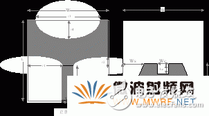
Figure 1 Schematic diagram of the antenna structure
In order to further reduce the return loss and achieve the requirements of the wide frequency band, the ground plate adopts a trapezoidal structure. The two sides of the conventional rectangular floor are chamfered, and a rectangular groove is opened at the center of the top end. The two chamfer sizes on the floor are Ws × Ls = 6 mm × 11 mm, and the rectangular groove size is Wc × Lc = 4 mm × 1.8 mm.
3 Optimization results and their analysisIn order to better study the influence of various parts of the antenna on the overall performance of the antenna, we carried out a series of parameter scanning and optimization through the commercial simulation software CST. Among them, r2 has an important influence on the overall impedance matching of the antenna. As shown in Fig. 2, by increasing or decreasing r2, the impedance matching of the antenna is deteriorated and the resonance point is reduced. Therefore, by optimizing, we finally choose r2 to be 2 mm. R3 can not only adjust the impedance matching of the high frequency band, but also reduce the lower frequency of the frequency band by affecting the current length. R4 has an effect on the impedance matching of the high frequency band, especially for the fourth resonant frequency point. The cut-and-grooved floor is an effective part of the antenna design, and the current distribution on the modified floor affects the impedance characteristics of the antenna. As a result, by cutting the corner of the floor, the bandwidth can be greatly expanded, and then opening the rectangular groove on the floor can not only increase the bandwidth but also improve the impedance matching in the entire passband. The effect of floor changes on return loss is shown in Figure 3. It can be seen that the antenna can completely cover the frequency band required for UWB communication, and the standing wave ratio VSWR is less than 1.5 in almost the entire frequency band.
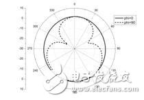
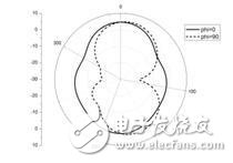
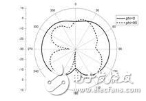
The radiation pattern of the antenna is shown in Figure 4. The performance of the antenna is very similar to that of a typical printed monopole antenna. The H-plane (phi = 0) exhibits almost omnidirectional, stable radiation characteristics, but it is degraded in the high frequency band because the electrical length of the antenna increases in the high frequency band, and the current radiation locally cancels in the far field. Or superimposed.

Figure 2 Effect of parameter r2 on return loss

Figure 3 Effect of floor changes on return loss
4 Conclusion
3.6 GHz
5.8 GHz
8.2 GHz
12.4 GHz
Figure 4 Radiation pattern of the antenna
This paper presents a compact planar printed monopole UWB antenna. The total size of the antenna is only 25×24×1.6mm3. Many parameters are optimized. By using a Y-shaped radiation patch with curved edges and chamfering and slotting on the floor, the impedance bandwidth is improved and the impedance is improved. Impedance matching. The optimized operating frequency band of the antenna is 2.96~14.6 GHz, and there is a stable omnidirectional radiation pattern in the entire frequency band. Therefore, the antenna is an ultra-wideband antenna with certain engineering application potential.
A port is an interface through which data is transferred between a computer and other devices (such as printers, mice, keyboards or monitors), networks, or other directly connected computers.
For the CPU, the port is used as one or more memory addresses for sending or receiving data. Dedicated hardware, such as an additional circuit board, places the data from the device in a memory address, and sends the data from the memory address to the device. Ports can be dedicated for input and output only. The port usually receives a specific type of plug for a specific purpose. For example, serial data interfaces, keyboards, and high-speed network ports all use different connectors, so it is impossible to plug the cable into the wrong port.
In programming, a port is a "logical connection location", especially in the Internet Protocol TCP/IP, a way for the client program to be assigned to a special service program on the computer. High-level applications that use TCP/IP protocols such as web protocol and hypertext transfer protocol have specially designated ports. From the perspective of port allocation, ports are divided into two categories: fixed ports and dynamic ports: Fixed ports (0~1023): use a centralized management mechanism, that is, subject to the assignment of ports by a management organization, which is responsible for issuing these assignments . Because these ports are closely tied to some services, we will often scan these ports to determine whether the other party has enabled these services, such as TCP 21 (ftp), 80 (http), 139 (netbios), UDP 7 (echo), 69 (tftp) and other well-known ports; Dynamic ports (1024~49151): These ports are not fixedly bound to a certain service. The operating system dynamically allocates these ports to each process, and the same process is allocated twice It is possible to assign to different ports. However, some applications are reluctant to use the dynamic ports allocated by the operating system. They have their own "branded" ports, such as port 4000 of the oicq client and port 7626 of the Trojan Binghe, which are all fixed and famous.
Pon Port,Nms,Web,Fttx Fttb Application,Fiber Optic Equipment
Shenzhen GL-COM Technology CO.,LTD. , https://www.szglcom.com