With the development of modern wireless communication technology to high frequency and high speed, people have put forward higher requirements for prefilters commonly used in high frequency communication. The bandpass filters currently used in RF systems mainly include dielectric ceramic filters and surface acoustic wave (SAW) filters. Due to the large volume and poor process compatibility of the dielectric ceramic filter, its further development is limited. Although the SAW filter can achieve a higher Q value and a smaller geometry, the finger width and gap of the interdigital electrode are inversely proportional to the operating frequency, which increases the difficulty of the lithography process and limits its high frequency application. Therefore, people began to study filters based on new materials and new structures.
The Film Bulk Acoustic Resonator (FBAR) is a new RF filter. FBAR devices are much smaller than traditional electromagnetic wave-based dielectric filters, which operate at higher frequencies and have better out-of-band rejection and lower insertion loss. Compared with SAW filters, bulk acoustic wave filters have certain advantages in terms of power capacity, filtering performance and frequency temperature coefficient, and their fabrication processes are compatible with semiconductor processes. In high frequency applications above Gyz, bulk acoustic waves ( BAw) filters are becoming the best choice.
1. Principle and structure of FBARThe FBAR adopts a sandwich structure of an electrode-piezoelectric film-electrode, and the inverse piezoelectric effect of the piezoelectric film converts the input high-frequency electric signal into an acoustic signal of a certain frequency. When the propagation distance of the acoustic wave in the piezoelectric film is exactly an odd multiple of the half wavelength, resonance occurs, wherein the acoustic wave loss at the resonant frequency is minimized, so that the acoustic signal of the frequency can pass through the piezoelectric film layer, and the signal of other frequencies It is blocked to output a signal with a specific frequency only at the output to achieve the filtering function of the electrical signal. The thickness of the piezoelectric film largely determines the resonant frequency of the FBAR, as shown in equation (1):
F≈υ/λ=υ/2d (1)
Where: v is the longitudinal sound velocity in the piezoelectric layer, and d is the thickness of the piezoelectric layer, which is the wavelength of the acoustic wave. In the actual resonator, there are other deposit layers that affect the resonant frequency, so equation (1) is only an approximate description. In general, the v of most materials is in the range of 3,000 to 11 000 m/s. According to the formula (1), the thickness of the piezoelectric layer should be controlled to several micrometers or less. Since the thickness of the piezoelectric layer plays a decisive role in the resonant frequency, precise control of the thickness during deposition of the piezoelectric film is particularly important.
The quality factor Q is a very important indicator for describing filter components. The Q value of the FBAR depends on the inherent loss of the piezoelectric film material and the loss of the bulk acoustic wave in the substrate, so that the total reflection of the acoustic wave formed at the electrode boundary can effectively increase the Q value. There are two main structures for achieving total reflection of sound waves. The most direct method is to form the piezoelectric layer and the electrode into a film structure or deposit them on a thin support film to form an air-solid interface; This is achieved by using a "sonic mirror" to form a reflective surface. This structure is called a "Solid Mounted Resonator (SMR)". The membrane structure can be divided into two situations depending on the manufacturing process: one is to use a bulk micromachining technique to deposit a layer of piezoelectric film on the substrate, and then remove part of the substrate to form a film structure with edge support suspended, such as Figure 1 (a). In addition, a surface micromachining technique may be employed, in which a sacrificial material is first deposited as a temporary supporting film, and then the sacrificial layer is removed by etching to obtain an air gap to form a reflecting surface, and the structure is as shown in FIG. 1(b). The FBAR of the suspended film structure causes the mechanical properties of the device to be degraded due to the large removal of the substrate, and the anisotropic etching of silicon is required during the preparation process, and the corrosion thickness is difficult to control, and 54.74 is also produced. The corrosion angle limits the increase in package density and increases the process difficulty. The use of surface micromachining technology is widely used without the need to process the reverse side of the substrate, reducing the process difficulty and being compatible with conventional IC processes.
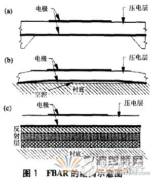
The FBAR of the SMR structure is alternately stacked with a plurality of materials of high acoustic impedance and low acoustic impedance to form a Bragg reflection surface. At the interface of each high-impedance layer and low-impedance layer, most of the sound waves are reflected. Since the layer thickness is 1/4 of the wavelength of the resonant frequency, the reflected waves are superimposed in the appropriate phase, and finally reach the approximation after multiple reflections. Total reflection. In general, 5 to 7 reflective layers are required to achieve a higher Q value. Since the multilayer reflective film of the SMR structure can serve as a support, it has better mechanical strength, but since more non-piezoelectric layers participate in resonance, its effective electromechanical coupling coefficient is smaller than that of the film structure. At the same time, the thicker reflective underlayer also makes it more difficult for the SMR to interconnect with the underlying circuitry for integration with other chips. In addition, a multilayer film having a complicated structure and precisely controlled thickness is prepared. There are certain difficulties in the process and the production cost is also higher.
2, FBAR piezoelectric film material technology2.1, the choice of piezoelectric film materials
The quality of the piezoelectric film has an important influence on the performance of the filter, so the choice of piezoelectric material is extremely important. The piezoelectric layer is a polycrystalline film, and grains with inconsistent directions severely reduce the piezoelectric coupling coefficient and the quality factor. Therefore, it is desirable that the c-axis orientations of all the crystal grains are completely uniform. Research on bulk acoustic wave filters shows that in order to obtain high-performance devices, it is necessary to improve the electromechanical coupling efficiency of piezoelectric films and reduce mechanical loss and leakage. Therefore, the fabrication of piezoelectric films with uniform orientation and precise thickness control is produced. The key to FBAR. Currently, piezoelectric materials for BAW filters are mainly aluminum nitride (AlN), zinc oxide (ZnO), and lead zirconate titanate (PZT). The three materials are compared below by several major performance parameters.
(1) Piezoelectric coupling coefficient k. It is an important physical quantity to measure the piezoelectricity of piezoelectric materials and determines the bandwidth that the filter can achieve. From this indicator, PZT is the most ideal, kt2 = 8.15; ZnO is second, kt2 - 7.5; A1N is slightly worse, kt - 6.5.
(2) Material loss. The smaller the loss, the higher the Q and the lower the insertion loss. In this respect, A1N and ZnO are superior to PZT, and further research on PZT materials is needed to reduce the inherent loss.
(3) Dielectric constant Er. A higher dielectric constant can reduce the size of the resonator. The Er of the first two materials is about 1O, and the Er of the PZT is higher than 400, which has obvious advantages in this respect. However, if the Er of the piezoelectric material is too large, the capacitance between the upper and lower electrodes will be large, which will cause the admittance between the input and output of the filter operating in the gigahertz band to be too large, and it is difficult to ensure the isolation of the stop band. Therefore, it is most suitable to make a filter of the Ghz band, and Er is about 100.
(4) Temperature coefficient. The temperature coefficient of temperature (TcF) has a great influence on the temperature drift of the device. Although ZnO has better piezoelectric performance than A1N, its TCF is a 60O & TImes; 10 / ° C, which is twice the temperature coefficient of A1N, thus making it Applications in many areas are limited. In order to improve the influence of TCF on the device, it is usually possible to grow a layer of positive temperature coefficient film material (usually SiO, TCF 85 & TImes; 10/oc) before the piezoelectric layer is deposited to achieve temperature compensation.
(5) Sound speed. Thin film piezoelectric layers can be used to make thin film acoustic wave devices with low sound velocity materials, so that the device size can be effectively reduced. However, from equation (1), the longitudinal sound velocity is closely related to the resonant frequency, and the high sound velocity can increase the center frequency of the filter. Among the above three materials, A1N has the highest sound velocity and is more advantageous in high frequency applications.
In addition to the aspects discussed above, there are other factors to consider when selecting a piezoelectric material, such as thermal conductivity, chemical stability, complexity of the fabrication process, and fabrication costs. At present, there are reports on BAW filters based on ZnO and A1N in foreign countries. The BA filters based on AlN have been commercialized for their performance and lower price than existing RF filters. Although PZT materials have better comprehensive performance, they have limited commercial applications due to lead, zirconium and other pollution elements; and the preparation process of PZT thin films that can be applied to BAw devices is still immature and is still in the research stage.
2.2. Preparation method of piezoelectric film
2.2.1 Preparation of AlN film
A1N thin films are widely used in acoustic wave devices and are ideal for making narrow bandwidth and medium bandwidth (5) BAW filters. FBAR requires the deposition of a piezoelectric film on an electrode. Therefore, the structure and properties of the electrode material have an important influence on the performance of the piezoelectric film. The electrode material must have high conductivity, low contact resistance and dielectric loss, high strength and low acoustic loss. The A1N film generally selects Pt as the bottom electrode 1, because the A1N crystal has a hexagonal wurtzite structure, the lattice constant a is 0.311 nm, and the mismatch with the Pt (111) plane is small. Other commonly used electrode materials are A1, W, Mo, etc. Reactive magnetron sputtering is the most important method for preparing A1N films. Nz was used as the reaction gas, and the reaction chamber was diluted with Ar, and high-purity Al was used as a sputtering target to form an A1N film. Parameters such as working pressure, nitrogen concentration, sputtering power and substrate temperature have a great influence on the crystal orientation and surface morphology of the film. 1. High deposition temperature can effectively improve the grain orientation consistency and electromechanical coupling coefficient]. However, excessive temperatures are clearly not compatible with the Ic process, so it is critical to grow high quality A1N films at lower temperatures. In addition, the A1N film can also be prepared by pulse laser deposition (PID), chemical vapor deposition (CVD) or the like.
2.2.2 Preparation of ZnO thin film
ZnO and A1N have similar crystal structure. The crystal lattice mismatch of C-plane and Pt(111) plane of ZnO crystal is 1.4V0. A well-crystallized ZnO thin film can be obtained on Pt surface. Therefore, Pt is often used as the bottom electrode material or Other materials use Pt as a buffer layer. There are many methods for preparing ZnO thin films, including MOCVD and PLD, and RF magnetron sputtering. The ZnO film prepared by PLD has the advantages of fast film formation speed and easy control of film stoichiometry. However, the phase structure of the film is difficult to control, stress is large, and it is not conducive to large-area film formation. M()cvD has low growth temperature and large film formation area. The controllability is good, but the raw materials are more volatile, the stability is poor, the film formation has more gaps and the cost is higher. Therefore, the preparation of ZnO piezoelectric films is mostly carried out by RF magnetron sputtering.
2.2.3 Preparation of PZT film
PZT materials have outstanding force-electric coupling properties and are the material of choice for making wide bandwidth BAW filters. The PZT film can also be prepared by sputtering, PLD, etc., but the currently used preparation method is a sol-gel method. It is a relatively low-cost film-forming method, which has the advantages of easy control of film components, compact structure, easy formation of large-area film, compatibility with IC process, etc. It is a widely used method for preparing PZT films in MEMS technology. Due to the serious mismatch between silicon and PZT, si itself will diffuse to PZT and react with TI in PZT. Therefore, when Si is used as the substrate, a transition layer must be grown. The commonly used structure is: Pt/si02/si And Pt/TI/si02/si. Ti can improve the bonding force between Pt and si()2, and the SiOz layer can prevent the electrode material from reacting or interdiffusion with the si substrate under high temperature conditions, and improve the interface characteristics. In order to obtain a film having a good orientation, a layer of PbTiOs is usually regenerated as a seed layer on Pt to improve the crystallization performance and lower the crystallization temperature. In addition, the Zr/Ti ratio can be adjusted, or appropriate doping (such as La, Mn, etc.) can be performed to modify the material to adjust the performance of the piezoelectric film; in the film preparation process, a rapid annealing process is often used to reduce the annealing temperature. , shorten the annealing time and increase the quality of crystallization. At present, although there are still many problems to be solved in the preparation of PZT piezoelectric films, it is undeniable that PZT still has broad application prospects in FBAR.
2.3. Analysis and characterization of piezoelectric films
In the preparation of piezoelectric films, the characterization of film samples is inevitably involved to optimize the process conditions. Commonly used analytical testing methods include: (1) X-ray diffraction (xRD) analysis of materials to understand the crystal phase structure and orientation of the film; (2) electron microscopic analysis, such as by scanning electron microscopy (sEM) and Atomic force microscopy (AFM) was used to observe the surface morphology of the film, to understand the uniformity, compactness and surface roughness of the film. The transmission film: microscope (TEM) was used to analyze the interface of each layer of the film; (3) electron spectroscopy analysis, such as The stoichiometry of the film is analyzed by XPS, EDS, etc.; (4) thermal expansion analysis, film stress analysis, and insulation resistance analysis. A high-performance piezoelectric film suitable for BAW devices can be obtained only by selecting a suitable preparation process and supplemented by scientific analytical characterization.
3. Principle, structure and modeling of BAW filterWhen designing filters, it is important to make the design process simple and fast in order to meet the design needs of different performance indicators. Considering that the thickness of FBAR is generally much smaller than its lateral dimension, a one-dimensional model of thickness direction can be approximated to analyze the characteristics of FBAR, and the impedance equation of FBAR is derived by one-dimensional acoustic and piezoelectric equations. However, this model is more complicated for the design of the filter, so it is necessary to introduce a simpler and more compact lumped parameter model to describe the FBAR. Figure 2 is a simple model paradigm called the "ButterworthVan-Dyke" (BVD) model. The BVD model can be derived from the impedance equation of a simple resonator, describing the electrical properties of the device at frequencies near the low frequency or resonance point.
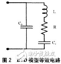
By measuring the impedance characteristic curve or transmission coefficient curve of the actually prepared FBAR, the series and parallel resonance frequencies fs and fp of the device can be obtained, and the static capacitance Cf and the impedance R value at the series resonance point can also be measured. Through the analysis of the equivalent circuit, the impedance expression of the resonator can be described as
Z=(1/jwCf)zs/zp
among them: 
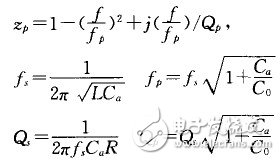
Therefore, the parameter values ​​of the discrete components of the equivalent circuit can be calculated by the following formula:

The parameter values ​​of the discrete components in the BVD model defined above are closely related. It is not possible to adjust the value of a component individually to improve the overall performance of the filter. The impedance characteristics of the BVD model are close to the actual application, and have the significant advantages of simple structure. Therefore, the BVD model becomes a preferred solution for designing filters.
Connecting a plurality of resonators in some way can constitute a filter that meets various needs. As shown in Figure 3, there are usually two connection methods: one is FBAR as the basic unit, and the filter network is formed by ladder type or grid type bridge; the other is to form the resonator by mechanical coupling. A filter that uses a property of FBAR-excited sound waves to propagate in the thickness direction to superimpose a plurality of resonators in a thickness direction to form a crystal stacked filter (SCF); or connect them by a coupling layer to form a coupled resonator filter (CRF). Filters of different structural forms have different advantages and disadvantages, so they can be connected to each other to form the required filter structure.
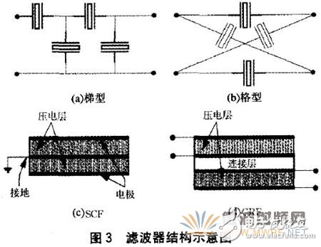
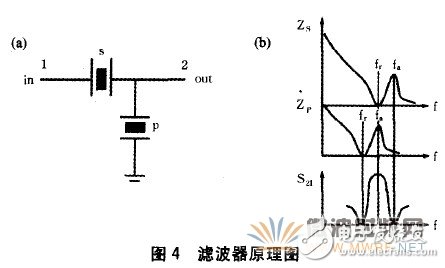
Fig. 3(a) is a ladder-type cascade filter. Since the FBAR unit can separately optimize the impedance and the center frequency during the manufacturing process, and the relatively simple connection method can be adopted, the ladder type cascade structure becomes the most A commonly used filter structure. The filter of the ladder structure is composed of a set of series resonators and a set of parallel resonators. Optimizing this structure is a balance that seeks low insertion loss and high suppression band attenuation; increasing the number of connected stages can effectively improve the out-of-band rejection attenuation, but it also increases the insertion loss due to the increased number of connected resonators. Big. The resonator has two characteristic frequencies, the impedance is the smallest at the resonance frequency point fr, and the impedance is the largest at the anti-resonance frequency point fa. Figure 4(a) shows the simplest cascaded filter structure consisting of a series resonator and a parallel resonator cascade. The anti-resonant frequency fa of the parallel FBAR is close to the resonant frequency fr of the series FBAR to achieve the passband center frequency of the filter; the anti-resonant frequency fa of the series FBAR constitutes the upper stopband attenuation point of the filter, and the resonant frequency fa of the parallel FBAR constitutes The lower stop band attenuation point of the filter. Figure 4(b) shows the corresponding transmission coefficient curve.
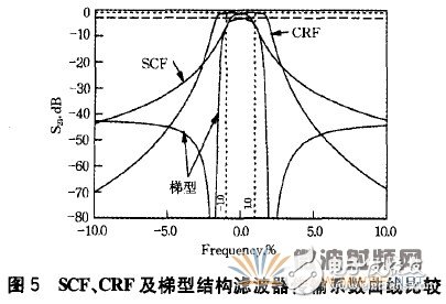
Compared to the ladder structure, the filter of the lattice structure has a larger bandwidth response, and at the same time, it is more suitable for the symmetrical circuit due to its balanced symmetrical structure. The SCF and CRF structure filters have better out-of-band rejection without increasing insertion loss, so they are more suitable for applications in high frequency, small size, and high stopband attenuation requirements. For the CRF structure filter, due to the existence of the coupling layer in the structure, the bandwidth and the center frequency can be easily adjusted by changing the type or thickness of the coupling layer material. However, the filters of these two structures need to deposit at least two piezoelectric films, which is more difficult in the preparation process; and the resonance mode of the whole component is affected by the resonance states of the upper and lower resonators, resulting in a spectrum becoming more complicated. Complex and difficult to analyze. Figure 5 is a comparison of the filter characteristics of the three structural filters. It can be seen that the CRF and SCF structures have better out-of-band rejection performance, and the CRF structure has a larger bandwidth response, but the ladder structure filter has more Steep roll-off curve. Therefore, it is possible to combine the three structures to obtain a better performance filter.
In the past 10 years, with the rapid development of wireless communication technology, a new generation of high-performance filters has become one of the hotspots of current research. BAW filters are highly competitive due to their excellent performance. This paper briefly introduces the structure, principle and related piezoelectric film materials of the film bulk acoustic wave filter. There are still some urgent problems to be solved in current BAW devices: how to obtain larger coupling coefficients to meet the bandwidth requirements of large data transmission in next-generation communication systems, how to improve the process level to ensure the matching of film thickness errors, and how to obtain A piezoelectric film in which the c-axis is uniformly oriented. Nevertheless, it is entirely convinced that with the advent of the third generation of mobile communication era, BAW filters will certainly show a broader application prospects with its unique advantages.
2.3 After fermentation Orange (Orange made enzyme solution navel orange), seized after the hand, breaking and other processes made of navel orange sauce.
Effects: lung, spleen shun gas, without any food additives, preservatives, is the first choice of children and senior citizens.
Companies registered capital of 35 million yuan, the end of 2014 the total assets of 48.69 million yuan, including fixed assets of 37.52 million yuan. The company's existing cooperation Orange cultivation base 7043.5 acres, the company production base is located in Jiangxi County Tech Industrial Park Chu Tan industrial area, covers an area of 120 acres, it has built a standard plant 9,000 square meters, Nissan 6000 kg Orange enzymes and other liquid enzyme products. Enzyme, known as enzyme, refers to a polymer substance having biocatalytic functionality. In the catalytic reaction system an enzyme, the reactant molecules are known as substrates, enzyme substrates by catalytic conversion to another molecule. Almost all cellular activity of enzymes involved in the process are required to improve efficiency. Similar to other non-biological catalysts, enzymes chemical reactions by lowering the activation energy to accelerate the rate of the reaction, most of the enzyme catalyzed reaction rate can be increased a million times; in fact, the enzyme is to provide an activation energy needs than another low way, so that more particles to have less than the activation energy of the reaction kinetic energy, thus speeding up the reaction rate. Enzyme as a catalyst, in itself is not consumed during the reaction, it does not affect the chemical equilibrium reactions. Positive enzyme catalysis, but also a negative catalytic effect, not only to accelerate the reaction rate, but also to reduce the reaction rate. And other non-living catalysts is different, having a high degree of specificity of enzyme, only a catalytic reaction or produce a particular specific configuration.
Enzyme Cream,Whitening Slimming Enzyme Cream ,Meal Replacement Diet Enzyme Cream ,Conditioning After Surgery Enzyme Cream
Guangdong ganzhou , https://www.tlqcjs.com