By using the inverter module R&S ZVA-Z110, Rohde & Schwar's high-end vector network analyzer can extend the coverage frequency to 75-110GHz millimeter wave band (W-band) R&S ZVA-Z110 is easy to operate and Helping customers save time and cost as a starting point for design, therefore, using a correct 4-port network analyzer to operate a pair of inverter modules does not require additional hardware circuitry. In recent years, multi-port measurements have become more and more Important The solution described in this article is the first to implement a complete multiport and balanced measurement in the W-band.
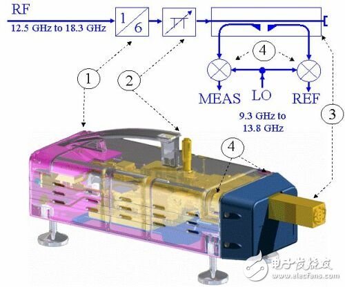
What is inside the inverter module?Figure 1 shows the CAD structure and block diagram of the R&S ZVA-Z110. The inverter module contains channel source frequency multipliers, adjustable waveguide attenuators, directional couplers for isolation reference and measurement signals. Wave mixer for down conversion

Figure 1: Transparent CAD structure and block diagram of the R&S ZVA-Z110 (adapter without test port)
S-parameter measurement of the filter
Let's take a mixer to set up a 90GHz bandpass filter as an example to discuss the test steps.
Step 1: Configure and set up
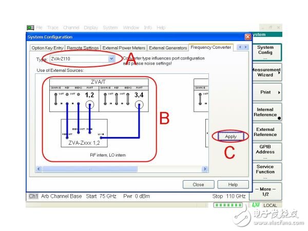
In the three areas A, B, and C shown in Figure 2, the following measurement configurations are made: select the inverter module model in area A, select the cable connection method in area B, click the application button in area C and connect the inverter module to the network analyzer ( See Figure 3), then adjust the frequency axis to 75 GHz to 110 GHz (see bottom of Figure 2). In addition, all measurement parameters of the inverter module are automatically set (eg RF and LO multiplier, optimal power level, reset) Setup, connection type WR10, and definition and selection of the waveguide calibration kit R&S ZV-WR10)

Figure 2: Settings dialog
Step 2: Calibration
This example uses TOSM calibration technology and the R&S ZV-WR10 Waveguide Calibration Kit for calibration (see Figure 3). The R&S ZV-WR10 Waveguide Calibration Kit also supports other calibration methods such as TRL, UOSM, TOM, TRM and OSM. It also includes sliding matching. The directionality and load matching index can be increased to 42dB and 40dB. Due to the radiation effect when the waveguide is open, the open circuit in the waveguide calibration component is replaced by an offset short circuit, which is made up of a spacer (execution band). λ/4 offset of the center frequency) and the composition of the crowbar
Step 3: Measurement
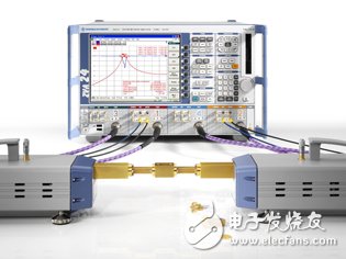
Figure 3 shows the use of a mixer R&S ZVA24 vector network analyzer and two R&S ZVA-Z110 inverter modules to measure all settings of a 90 GHz bandpass filter. Filters with high rejection characteristics. High dynamic range R&S ZVA The -Z110 inverter module sets a new dynamic range standard with a typical value of 110dB, which can easily meet the high dynamic requirements of measuring filters. Users can increase the measurement bandwidth, such as increasing to 1kHz for higher measurement speed.

Figure 3: Setting of full millimeter wave measurement with 90 GHz bandpass filter with R&S ZV-WR10 waveguide calibration kit
In addition to filter testing, the Z110 is also suitable for a variety of other applications, including: 1. Due to the built-in W-band attenuator, it can provide very low excitation levels, so similar applications such as low-noise amplifier testing will not There are any problems. 2. It can be used in particle-sensitive environments on compact designs and production lines that require fast scanning, such as on a wafer probe station. Passive cooling without a fan is another advantage. 3. For the millimeter wave band. Multiport and balanced port measurement applications
Multiport measurement
So far, multiport and balanced port measurements have been limited by mixer settings to approximately 50 GHz bandwidth, but many applications in the W band use balanced or multiport devices (such as ranging radar, defense, and aerospace applications) to utilize R&S ZVA. -Z110 inverter module and R&S ZVT20 vector network analyzer, can provide up to 6 measurement ports
Three-port measurement of directional coupler
1. Why use three-port measurement?
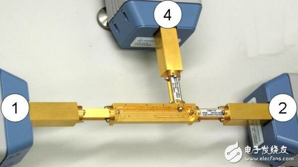
With three inverter modules and a suitable vector network analyzer, a three-port coupler measurement can be done in one connection (Figure 4). This saves measurement time and allows simultaneous measurement of all 3&TImes; 3S parameters without the need Multiple connections and multiple 2-port calibrations replace multiple 2-port calibrations with full 3-port calibration for more accurate measurements

Figure 4: Three-port measurement requires only three inverter modules
2. Measurement setup
The R&S ZVT20 can use up to 4 inverter modules without the need for an external signal source. This solution is very compact, requires no additional hardware and provides high measurement speed. In the three-port application mentioned above, only three The measuring ports 5 and 6 of the inverter module R&S ZVT20 provide the local oscillator signal for the inverter module. If the mixer settings are required, the external Wilkinson splitter can also be used to assign the local oscillator signal to all the inverter modules.
UOSM calibration
Desktop Phone Holder,Desktop Mobile Phone Holder,Adjustable Desktop Phone Holder,Universal Desktop Cell Phone Holder
Ningbo Luke Automotive Supplies Ltd. , https://www.car-phone-holder.com