Since the phased array technology that appeared in the late 1930s has been applied to military radar systems, the phased array antenna system has shown its advantages in terms of volume, weight, reaction speed, power consumption, and range of application, and has caused Satellite mobile communications, government emergency department systems and other civil concerns. In recent years, because dual-polarized antennas have dual-channel communication in the same frequency band, improve communication capacity, realize duplex operation, improve system sensitivity, and resist multipath effects, they are increasingly favored by people. The currently used dual-polarized antenna can achieve a combination of three orthogonal polarization modes: vertical and horizontal polarization, ±45° polarization, and left and right circular polarization. This article will introduce a new type of dual-polarized antenna combining horizontal polarization and vertical polarization.
1 Design of dual polarized antennaThe currently used dual-polarized antennas are mainly implemented by two-layer or multi-layer circuits, and different polarizations are realized by antenna arrays of different layers. The phased array antenna used in this design can realize dual polarization on the same level. As long as the feeding mode of the microstrip patch unit is adjusted, two polarization modes of horizontal polarization and vertical polarization can be realized, thereby realizing bipolar Turn. The use of this new type of dual-polarized antenna enables vector reception of satellite signals and displays its unique advantages in mobile carrier communication systems.
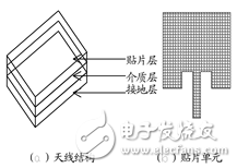
The dual-polarized antenna structure used in this paper is shown in Fig. 1. (a) is an antenna structure composed of a patch layer, a dielectric layer and a ground layer. Figure (b) shows the basic structure of the microstrip patch unit. Two polarization modes, horizontal polarization and vertical polarization, can be realized by adjusting the microstrip patch unit. It is located on the patch layer, and two polarization modes of horizontal polarization and vertical polarization can be realized by different feeding methods.
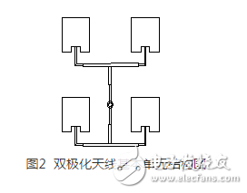
The basic unit structure diagram of the dual-polarized antenna designed according to the design index and the use requirements is shown in Fig. 2. This structure can realize the linear polarization of the antenna in one direction. In the dual-polarized antenna array used in this paper, each antenna element has only one polarization direction, and double polarization can be realized on the same layer by adjusting the feeding mode of each antenna basic unit.
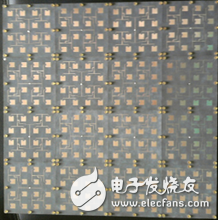
The antenna array used in this paper can receive signals that it cannot receive compared with the traditional single-line polarized antenna, and can increase the gain by 3dB with a single circularly polarized antenna. Compared with the existing dual-polarized antenna, the structure is simple and easy to implement, and the cost of the phased array antenna can be greatly reduced. According to the antenna principle described above, we have formed a new type of dual-polarized antenna according to the two polarization modes, and the antenna is shown in Figure 3.
We actually tested the designed 4&TImes;4 microstrip antenna array in a microwave darkroom. The length, width and height of the microwave darkroom are 15m, 9m and 9m respectively. The distance between the transmitting antenna and the receiving antenna used for testing is 10m, and the height of the test antenna from the ground is 2.5m. 4 is a V-plane pattern of the antenna array at 12.5 GHz. Figure 5 is a H-plane pattern of the antenna array at 12.5 GHz, respectively.
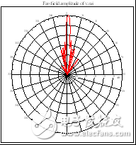
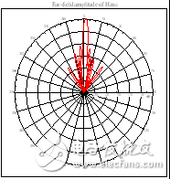
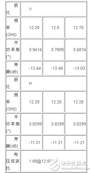
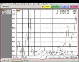
As can be seen from the above two figures, the antenna pattern is substantially symmetrical about the maximum value of the main lobe. Table 1 shows the actual test data of the antenna array on the H-plane. Figure 6 shows the standing wave test diagram of the antenna array. In the range of 12.25 to 12.75 GHz, the measured standing wave of the antenna is less than 2.0.
This paper mainly introduces a new design scheme and actual test results of a dual-polarized antenna. This design realizes the dual-plan design of the antenna by adjusting the feeding mode of the most basic patch unit, and realizes the simplification of complicated problems. The final design of the physical test data is basically consistent with the simulation results, in line with the design requirements. The dual-polarized antenna realized by the design has the advantages of simple structure, light weight, convenient use and high receiving efficiency. A new attempt is made for the development of future phased array antennas, which will have certain influence and promotion on the design of dual polarized antennas.
220W Medical Power Supply,220W Medical Device Power Supply,220W Medical Power Adapter,220W Rade Power Supplies
Shenzhen Longxc Power Supply Co., Ltd , https://www.longxcpower.com