Modern civil and military facilities use a large number of electronic devices, and the electromagnetic environment is complex and the mutual interference is serious. In general, communication device transceivers on cars, boats, and airplanes are integrated. Taking a short-wave communication device as an example, the residual signal of the transmitter generates a level of 120 dBμV (ie, 13 dBm) or higher at the input of the receiver. The weak signal level that the receiver needs to receive may be only -6 to 0 dBμV (ie, -117 to -113 dBm). Therefore, the dynamic range of the signal processed by the receiver is required to be as high as 120 to 126 dB. In addition, the high-level interference signal is only a few tens of kilohertz from the received signal frequency. Therefore, the high-level interference signals and their intermodulation products generated in the receiver can seriously affect the output signal-to-noise ratio of the receiver. In order to reduce this effect, the receiver is required to have the following properties:
High selectivity, the dynamic range of the receiver should be as large as possible;
High linearity, reducing the intermodulation products generated by the out-of-band high-level interference signal in the passband of the channel filter before channel filtering;
• Very low local oscillator phase noise to prevent adjacent interfering signals from converting local oscillator noise into the receiver channel bandwidth.
The receiver RF front-end, which is an important part of the receiver, is a key component of the receiver's dynamic performance and operates before the IF amplifier. Such as dynamic range, intermodulation distortion, -1dB compression point and third-order intermodulation interception point, etc., are directly related to the performance of the receiver front end. The RF front-end design techniques in the receiver are described below.
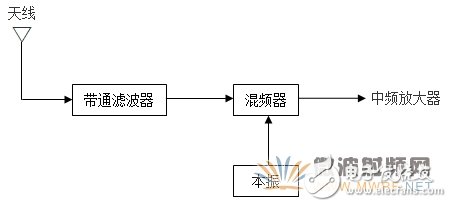
Several structures of the RF front end 1. The simplest RF front end structureThe receiver front-end circuit has several different structures. Figure 1 shows one of the simplest forms. This configuration has no RF amplifier. After the bandpass filter, there is only a mixer and a local oscillator. The input of the bandpass filter is from the antenna, and its output is passed through a mixer to the IF amplifier for subsequent processing.

Figure 1 Simple RF front-end structure
The main features of this structure are: first, the cost required in implementation is less than other structures; second, avoiding consuming the dynamic range of the mixer due to the processing of useless energy.
The bandpass filter has good forward performance (within the passband range) and good reverse isolation performance. This prevents the local oscillator signal energy from radiating to the antenna, thereby preventing the antenna from radiating these signal energies. The bandpass filter has three main tasks:
Limit the bandwidth of the input signal to minimize intermodulation distortion;
· Reduce the spurious response, mainly the image frequency and 1/2-IF frequency problem;
• Suppress the energy radiated by the local oscillator to the antenna.
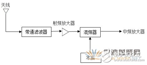
The second front-end structure is shown in Figure 2. This structure uses an RF amplifier. The gain of the RF amplifier is low - typically less than 20 dB. Gains above 20 dB may compromise system stability and may not achieve intermodulation intercept points.

Figure 2 Front-end structure using a RF amplifier
The purpose of the RF amplifier is to isolate the mixer while amplifying the signal before mixing. This amplification compensates for losses in the mixer and bandpass filter. The main feature of the RF amplifier is the improved isolation between the mixer/local oscillator circuit and the antenna circuit.
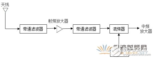
3, a more complete front-end structureThe third structure is shown in Figure 3. Similar to the above two structures, the structure also has a mixer and a local oscillator circuit, or a converter including a mixer and a local oscillator. This structure differs from the former structure in that a band pass filter is added.

Figure 3 More complex front-end structure
Both filters can have the same center frequency, but this is not the best design method. Generally, the frequency of the second filter is adjusted to the mirror frequency, which is the intermediate frequency of the radio frequency plus or minus 2 times, and the RF signal is located on both sides of the local oscillator frequency. Thus, the image frequency, like the RF signal, is processed the same in the mixer and can therefore pass through the system as an effective signal.
Stainless Steel Bright Line,Stainless Steel Lock Wire,Inox Ss Stainless Steel Wire,Gasless Stainless Steel Mig Wire
ShenZhen Haofa Metal Precision Parts Technology Co., Ltd. , https://www.haofametals.com