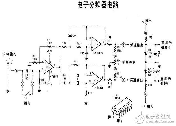
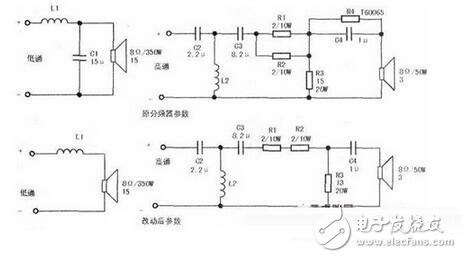
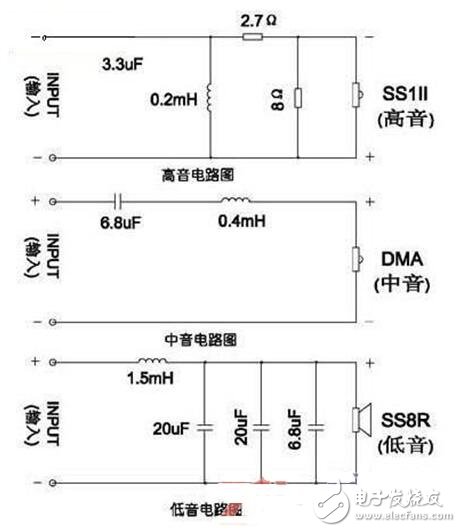
The following figure shows a simple crossover circuit diagram. Among them, the low-pass filter composed of L1 and C1 selects the frequency division point of 200-54 at 1.5kHz. Here, its frequency division point is appropriately increased, mainly because the unit has good characteristics, and more importantly, the audio power is mostly concentrated in the middle. Low frequency, properly increase the cut-off frequency of the low-frequency unit, you can give full play to the unit's strengths, the sound will be more full and powerful. If the crossover point is too low, not only the unit advantage is lost, but also the burden on the intermediate frequency unit will be increased, causing amplitude overload, increased distortion and other disadvantages.
Although the effective frequency response of the intermediate frequency unit is up to 800Hz ~ 10kHz, the bandpass filter composed of L2, L3 and C2, C3 only takes its 1.5 ~ 6kHz band, which is also its golden frequency band. The high-pass filter composed of L4 and C4 sets the frequency division point of YDQG5-14 to 6kHz, and the lower cut-off frequency of this unit is also higher, which will make it easier to play its specialty in the high frequency band. Due to the reasonable selection of the crossover point, each of the three units works in the frequency band with the highest acoustic efficiency, so the overall sensitivity of the system is also 1 ~ 2dB higher than the average characteristic sensitivity of each unit.
The frequency divider has few components and the circuit is very simple. The minimum requirements for the frequency dividing capacitor are good high frequency characteristics, small loss and capacity error. The current polypropylene CBB non-polar capacitor has a loss tangent value of only 0.08% to 0.1%. It has excellent high-frequency performance, small size, no inductance, and low cost. This speaker adopts CBB21 and CBB22 capacitors with a voltage of 63V. For 9.4 uF, use two 4.7 uF in parallel.


The speaker splitter is a combined filter, which can separate the sound signals of different frequency bands, respectively amplify them, and then send them to the speakers of the corresponding frequency bands for replay, so that the playback characteristics of each frequency are more balanced and consistent .
The role of speaker crossoverThe function of the crossover is equivalent to the "brain" in the speaker. The crossover plays a vital role in the quality of the sound. The frequency divider can be used to send high-frequency signals to the tweeter and low-frequency signals to the woofer, so that the high-frequency and low-frequency signals can go their own way. Give full play to make the playback characteristics of each frequency more balanced. So it is not difficult to see that a well-designed crossover can better play the characteristics of the unit to make the sound play a better quality.
Circuit diagram of speaker crossover
From the working principle, the frequency divider is a filter network composed of a capacitor and an inductance coil. The treble channel only allows high-frequency signals to pass and blocks low-frequency signals; the bass channel is the opposite, only allows bass to pass and blocks high-frequency signals; The frequencies between them can pass through, and both high-frequency and low-frequency components will be blocked.

The sound box frequency divider is to process the music signal output by the power amplifier through an internal filter element, so that the signal of a specific frequency of each unit passes. The speaker crossover circuit diagram can clearly show how to effectively according to the different characteristics of the speaker unit, through the optimization of the combination to make each unit grow up and avoid weaknesses, to maximize their respective potential.
In the design process of the speaker crossover circuit diagram, if you need to balance the difference between the flexibility of the high and low units, you can also participate in the attenuation resistance; if you need to make the impedance curve of the speaker flatter, you can also increase the impedance composed of resistance and capacitance Compensation network.
Loudspeaker three-way crossover circuit diagramThe crossover is the "brain" in the speaker, which is crucial to the sound quality. The music signal output by the power amplifier must be processed by the filter element in the frequency divider to let the signal of a specific frequency of each unit pass. It is necessary to design the frequency divider of the speaker scientifically, reasonably and rigorously to effectively modify the different characteristics of the speaker unit and optimize the combination so that each unit can develop its strengths and avoid its shortcomings. Only smooth, accurate image phase can make the high, middle, and low-pitched music layer have clear, coherent, bright, comfortable, wide, and natural sound quality effects.
The speaker divider is a combined filter that can divide the sound signal into several frequency bands. The audio two-way frequency divider is composed of a high-pass filter and a low-pass filter, while the three-way frequency divider adds a band-pass filter. This article describes a simple three-way crossover circuit diagram of the speaker, the input can be connected to the same output. as the picture shows.

Ethernet cable wiring serviced offered for CAT5 and CAT6 by UTP, STP FTP. And DB and RJ series in different pins, all related tool is available. We have developed a tradition of high-tech engineering, prototyping, and quality custom cable manufacturing at very competitive pricing. Also with professional flow chart (wire cutting-stripping-copper twisting-crimping-crimping 100% inspection-soldering-molding-asssembling-braiding-testing-FQC100% -OQC) , which can help us support customers with stable quality.Such as cat 5 wiring cable,cat 5 cable.
Ethernet Cable Wiring,Cat 5 Wiring Cable,Custom Wire Assembly,RJ45 Cable,Cat 5 Cable,Cat 5 Wiring Cable
ETOP WIREHARNESS LIMITED , http://www.wireharness-assembling.com