1 Introduction
At present, power factor correction has been developing in the direction of high efficiency, simple structure, easy control, and reduced EMI. Therefore, bridgeless Boost PFC circuits have attracted more and more attention as an effective way to improve efficiency.
The bridgeless Boost PFC circuit omits the rectifier bridge of the traditional Boost PFC circuit, and at least one diode is turned on at any time than the conventional Boost PFC circuit, so the conduction loss is reduced, and the efficiency is greatly improved. The bridge Boost PFC circuit was compared and analyzed, and the two representative bridgeless circuits were tested and EMI tested.
2 Conducted EMI analysis of switching converter circuits
Electromagnetic interference (EMI) can be divided into two types: conducted interference and radiated interference. When the harmonic level of the switching converter circuit is in the high frequency range (frequency range above 30 MHz), it appears as radiated interference, and when the switching converter circuit Harmonic levels appear as conducted interference in the low frequency range (frequency range 0.15 ~ 30 MHz), so the switching converter circuit is mainly conducted interference. Conducted interference currents can be divided into two categories according to their flow paths: one is differential mode interference current and the other is common mode interference current.
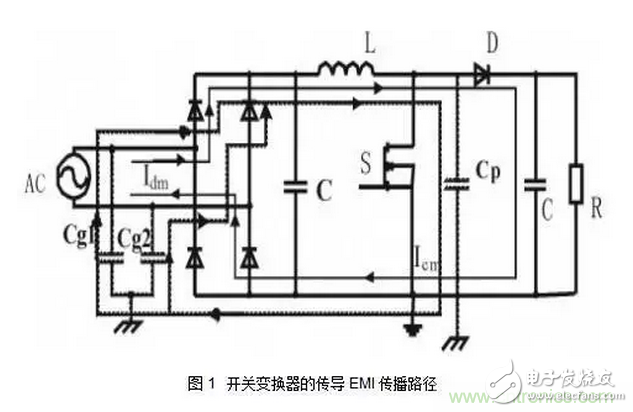
Taking the Boost circuit shown in Figure 1 as an example, the EMI of the switching converter circuit is analyzed. The pulsating current generated during the rectification of the circuit introduces a large amount of harmonics to the circuit system, although there is an electrolytic capacitor C on the rectified output side. Except for some harmonics, but because the electrolytic capacitor has a large equivalent series inductance and equivalent series resistance, it is impossible for the electrolytic capacitor to completely absorb these harmonic currents, and a considerable part of the harmonic current has to be equivalent to the series inductance of the electrolytic capacitor. Interacting with the equivalent series resistance, the differential mode current Idm is returned to the AC power supply side, and the propagation path of the differential mode current is shown by the solid line with an arrow in FIG. The high-frequency on-off of the switch tube generates a high dv/dt, which interacts with the parasitic capacitance Cp between the power tube and the heat sink to form a common mode current Icm. This common mode current reaches the ground through the heat sink, and the ground line The mode current is coupled to the phase and neutral lines on the AC side through parasitic capacitances Cg1 and Cg2 to form a common mode current loop. The propagation path of the common mode current is shown by the dotted line with an arrow in FIG.

The differential mode currents formed in various common bridgeless Boost PFC circuits are identical with the same main circuit parameters. The difference is the common mode current caused by the position of the switch tube and the addition of the diode. Therefore, the main analysis of this paper is the common mode interference in various circuit structures. The parasitic capacitance of each point is replaced by the magnitude of the potential change between the points and the input side zero line and the frequency change.
3 Introduction to common bridgeless Boost PFC circuits
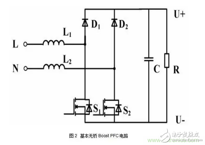
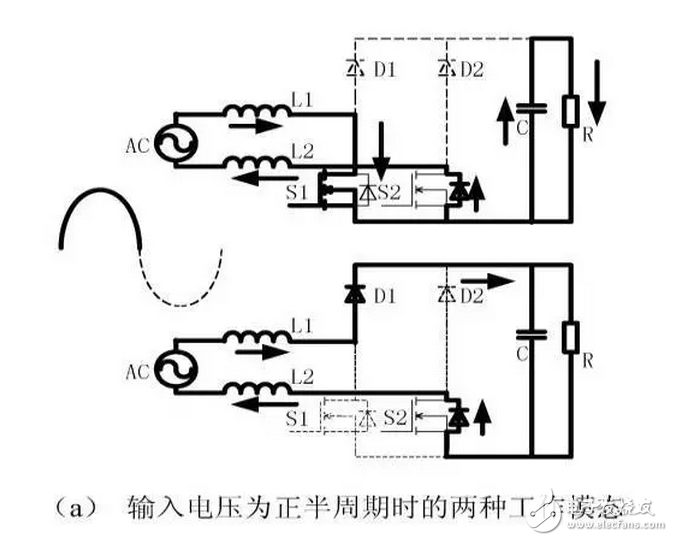
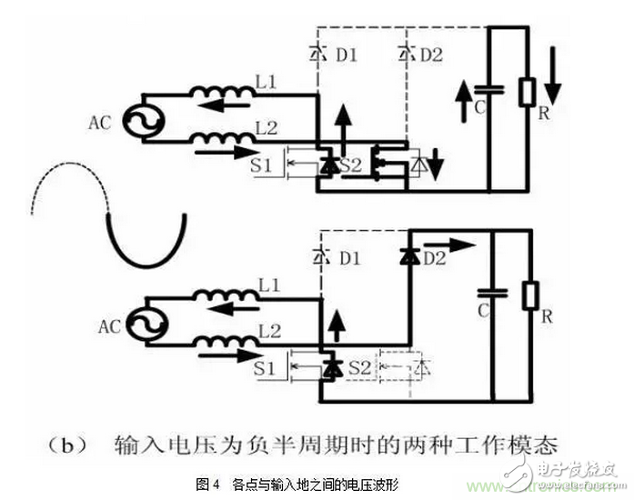
The basic structure of the main bridgeless PFC main circuit is shown in Figure 2. It consists of two fast recovery diodes (D1, D2) and two switching tubes (S1, S2) inductors (L1, L2). The driving signals of the switching tubes S1 and S2 are the same, and the two tubes are turned on and off at the same time. For the positive and negative half cycles of the power frequency AC input, the bridgeless Boost PFC circuit can be equivalent to a combination of two Boost PFC circuits with opposite supply voltages, one for the inductors L1 and L2, the switch tubes S1, D1 and the switch. The body diode of the tube S2 is composed, and its conduction mode is as shown in FIG. 3a; the other group is composed of the body diodes of the inductors L1 and L2, the switch tubes S2 and D2 and the switch tube S1, and its conduction mode is as follows. Figure 3b shows. It can be seen from Fig. 3 that only two semiconductor devices are turned on at any one time, and one diode is turned on less than the conventional PFC circuit with a rectifier bridge, thereby reducing the conduction loss and improving the efficiency. However, its shortcoming is that the inductor current sampling is difficult. It can be seen from Fig. 3 that the circuit structure cannot obtain the current sampling with the same polarity on one loop, so it is necessary to construct a complex inductor current detecting circuit [4]. In addition, the biggest problem of this circuit is that the common mode interference is large. The waveform between the points in Figure 2 and the input zero line can be analyzed to obtain the waveform shown in Figure 4, where Vbus is the output DC bus voltage and Vline is instantaneous. Input voltage. It can be seen from Fig. 4 that the potential between the U-side, the A-point, the B-point of the busbar and the side of the power supply floats with the switching frequency [5], so a large parasitic capacitance occurs between the above points and the input power ground. Common mode interference is more serious, and EMI problems are more prominent.


LED Par can
LED PAR LIGHT Series
54X3W rgbw; 18x12w RGBW;24x12w RGBW is hot selling in the market. It have waterproof and non-waterproof
Features:
- RGBWA+UV color, 6-in-1 LEDs, excellent color mixing
- quiet working, suitable for quiet applications like theater, studio,etc
-
suitable for events where indoor/outdoor flexibility is needed
- Adjustable PWM (Pulse Width Modulation) to avoid flickering on camera
- Advanced optics provide exceptional color mixing and high efficiency
- Smooth dimming curves for eliminate flicker and choppiness in fades
Our company have 13 years experience of LED Display and Stage Lights , our company mainly produce Indoor Rental LED Display, Outdoor Rental LED Display, Transparent LED Display,Indoor Fixed Indoor LED Display, Outdoor Fixed LED Display, Poster LED Display , Dance LED Display ... In additional, we also produce stage lights, such as beam lights Series, moving head lights Series, LED Par Light Series and son on...
LED Par Light Series,Led Par Can Lights,Par Can,Led Par Stage Light
Guangzhou Chengwen Photoelectric Technology co.,ltd , https://www.cwleddisplay.com