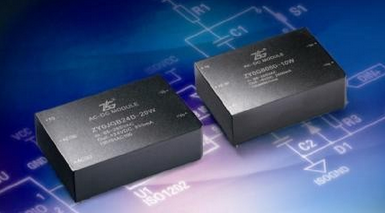
The same input and output voltage, the same power, the same package, different manufacturers of power modules, which performance is better? For a good performance power module, there are many projects to be tested, and these performances are closely related. This article selects the performance of several aspects to compare and explain.
1, stable and reliable
Stable reliability is fundamental. If the power module is stable and reliable during operation, it cannot be guaranteed. Other performances are not mentioned.

From a design point of view, it is necessary to consider that when the module is in the harshest environment, the electrical stress and thermal stress of each device in the module are within the allowable range and ensure a certain margin, and should be stable when the system is subjected to certain interference.
From the application point of view, although some performance can not be tested, but the power supply stability reliability can be tested according to the specification limit test conditions, such as the highest minimum voltage, the highest minimum temperature, the maximum load, etc.; the circuit can also be recommended according to the specification as shown in Figure 1. Test module surge immunity, static immunity, pulse group immunity, etc.; also test module continuous short circuit, repeat switch machine, etc.

Figure 1 recommended circuit
Of course, these tests are inherently destructive and can cause certain damage to the module and should not be used on the product after testing.
2. Capacitive load and overcurrent protection
The greater the capacitive capacity of the power supply, the higher the current limit setting. High power stresses are caused during startup and output shorts, even saturating the transformer. On the other hand, in the range of the rated load from the rated load to the current limit point, the power supply cannot achieve overcurrent protection, which will seriously affect the reliability and life of the power supply.
3, load adjustment rate and minimum load requirements
For a single output power supply, there is generally no minimum load requirement. However, when the load is reduced to less than 10% of the rated load, in order to reduce the power supply no-load or light-load power consumption, it will enter the intermittent operation mode. Although it does not affect its normal operation, its ripple may increase and auditory noise may occur. Therefore, the power should also be considered when selecting a power module. If the maximum load is less than 1W, it is obviously not suitable to select a power supply of 10W or more.
In addition, for dual and more output power supplies, each path is typically required to have at least 10% of rated load. Taking the dual output as an example, if the main road is fully loaded and the auxiliary road has a rated load of 10% or less, the auxiliary circuit output voltage will be higher than the rated value; if the main road has a rated load of 10% or less, and the auxiliary road is fully loaded Will cause the auxiliary circuit output voltage to be much lower than the rated output value.
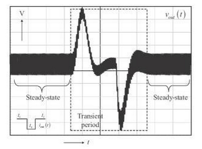
In addition, it is worth noting that if the main road suddenly changes from heavy load to very light load or vice versa, it will cause the auxiliary circuit voltage to undershoot or overshoot. Obviously this means that the "big move" of the main road will probably cause the auxiliary road to work abnormally.
The module itself can add a larger dummy load, which of course increases its losses. When selecting a power module design system, especially for multiple output modules, the lightest load problem should be considered.

Figure 2 Upper and lower punches
4, other basic performance
Other performances that need to be compared are: ripple noise, voltage accuracy, voltage regulation, turn-on overshoot, rise time, power-down hold time, no-load power consumption, efficiency, etc. However, when testing, the standard test method should be adopted. For example, when testing ripple noise, the bandwidth should be limited to 20M, and the method of measuring or parallel line testing should be used.
5, summary
In summary, comparing only one or two aspects of performance, it is unwise to conclude that a particular power supply is better. Designers may often sacrifice another performance for some other performance.
For the application, the module should be selected according to the actual situation, usually under the premise of stable and reliable, the application can be satisfied, and it is not necessary to pursue the best performance. The design of the module is usually to meet the general requirements. If, in some cases, the specific application cannot be met, the module design manufacturer should be contacted to provide a corresponding solution.
For the designer, attention should be paid to the interaction of various performances to optimize overall performance.
1.27mm (0.050") Pitch Female Headers
Like the 1.27mm pitch male header, the 1.27mm pitch female header is used in densely-packed devices, requiring space-saving connections. The low profile, 1.27mm pitch female header addresses the need for connecting a variety of board-to-board configurations, with vacuum pick and place that makes it suitable for high volume automated manufacturing. It can be available in varying elevated stack heights, pass-through, rugged, high-density, and in numerous low-cost designs.
Antenk offers 1.27mm pitch female headers in either SMT or THM orientation at high quality and affordable China-quoted price that snuggly fits with the pins of a male header and acts as a receptacle.
Assembly and service is simple with either vertical (straight), elevated or at a right angle orientation, which can dissipate current of about 1.0 A or less in a tape and reel packaging. The filleted corners can also remove shadowing allowing optimization of LED output.
The 1.27mm pitch female headers are commonly found in PC`s and are also made to work in Arduino boards, Arduino Pro and Arduino Mega with either single or double-row female headers, facilitating connections for programming and incorporation into other circuits. They have the perfect height for clearing the USB-B connector and great for stacking multiple shields.
Female header always called as [Header connector", Antenk provide widely range of header connector, from 2.54mm (.100″ inch) pitch to 1.0mm (.039″ inch) pitch. The number of pins (contacts) is from 2 to 40 pins per orw. There are three type: Straight (Dip Vertical), Right angle, SMT (surface mount).
If you can not find the items you interest from above items, welcome to contact us, and you will always get fully responsive from us.
Applications of 1.27mm Pitch Female Headers
Its small size is most suitable for PCB connections of small equipment and devices such as:
Arduino Boards
Architectural and sign lighting
Retail and display lighting
Fluorescent LED retrofit lighting
Cabinet or furniture lighting
Commercial / residential cove lighting
WiFi equipment
Gaming consoles,
Measurement instruments
Medical Diagnostic and Monitoring equipment
Communications: Telecoms and Datacoms
Industrial and Automotive Control and Test
At one side of this female header is a series of pins which can either be mounted and soldered directly onto the surface of the PCB (SMT) or placed into drilled holes on the PCB (THM).
Through-Hole (Poke-In)
Best used for high-reliability products that require stronger connections between layers.
Aerospace and military products are most likely to require this type of mounting as these products experience extreme accelerations, collisions, or high temperatures.
Useful in test and prototyping applications that sometimes require manual adjustments and replacements.
1.27mm vertical single row female header, 1.27mm vertical dual row female header, 1.27mm Elevated single row female header, 1.27mm Elevated dual row female Header, 1.27mm right-angle single row female header and 1.27mm right-angle dual row female header are some examples of Antenk products with through-hole mount type.
Surface-Mount
The most common electronic hardware requirements are SMT.
Essential in PCB design and manufacturing, having improved the quality and performance of PCBs overall.
Cost of processing and handling is reduced.
SMT components can be mounted on both side of the board.
Ability to fit a high number of small components on a PCB has allowed for much denser, higher performing, and smaller PCBs.
1.27mm Right-angle Dual Row female header, 1.27mm SMT Single row female header, 1.27mm SMT Dual row female header and 1.27mm Elevated Dual Row female Header are Antenk`s SMT female headers.
Soldering Temperature for 1.27mm Pitch Female Headers
Soldering SMT female connectors can be done at a maximum peak temperature of 260°C for maximum 60 seconds.
Pin-Type: Vertical (Straight) and Right-Angle
1.27mm pitch female headers may be further classified into pin orientation as well, such as vertical or straight female header or right-angle male header.
Vertical or Straight Female Header Orientation
One side of the series of pins is connected to PCB board in which the pins can be at a right-angle to the PCB surface (usually called "straight" or [vertical") or.
Right-Angle Pin Female Header Orientation
Parallel to the board's surface (referred to as "right-angle" pins).
Each of these pin-types have different applications that fit with their specific configuration.
PCB Connector Stacking
Profile Above PCB
This type of configuration is the most common way of connecting board-to-board by a connector. First, the stacking height is calculated from one board to another and measured from the printed circuit board face to its highest insulator point above the PCB.
Elevated Sockets/Female Headers
Elevated Sockets aka Stacked sockets/receptacles or Mezzanine are simply stacked female headers providing an exact distance requirement between PCBs that optimizes electrical reliability and performance between PCB boards.
Choosing this type of stacking configuration promotes the following benefits:
Connector Isolation - the contacts are shrouded preventing cable connection mishaps and good guidance for the mating header connectors.
For off-the-shelf wireless PCB module, stacking height is optimized with elevated sockets.
Offers superior strength and rigidity.
Polarisation prevents users from inverted insertion.
Single, Dual or Multiple Number of Rows
For a 1.27mm straight or vertical female header, the standard number of rows that Antenk offers ranges from 1 to 2 rows. However, customization can be available if 3 ,4 or n number of rows is needed by the customer. Also, the number of contacts for the single row is about 2-40 pins while for dual row, the number contacts may vary from 2-80 pins.
Pin Material
The pins of the connector attached to the board have been designed with copper alloy. With customer`s demand the pins can be made gold plated.
Custom 1.27mm Pitch Female Headers
Customizable 1.27 mm pitch female headers are also available, making your manufacturing process way faster as the pins are already inserted in the headers, insulator height is made at the right size and the accurate pin length you require is followed.
Parts are made using semi-automated manufacturing processes that ensure both precision and delicacy in handling the headers before packaging on tape and reel.
Tape and Reel Packaging for SMT Components
Antenk's SMT headers are offered with customizable mating pin lengths, in which each series has multiple number of of circuits, summing up to a thousand individual part number combinations per connector series.
The tape and reel carrier strip ensures that the headers are packaged within accurately sized cavities for its height, width and depth, securing the headers from the environment and maintaining consistent position during transportation.
Antenk also offer a range of custom Tape and reel carrier strip packaging cavities.
Pcb Connector,1.27Mm Female Pin Header,1.27 Header connecto,1.27Mm Pcb Header,1.27Mm Pcb Connector,0.050" Female Headers,1.27mm Female Pin Header SMT, 1.27mm Female Pin Header THT
ShenZhen Antenk Electronics Co,Ltd , https://www.atkconnectors.com