Virtual surround processor chip MM1454
MM1454 is a Q Surround virtual processor IC developed by Mitsubishi Corporation, which can realize the sound algorithm developed by Q SOUND Labs. When the stereo signal with Dollby Pro logic coding in the left / right (L / R) channels is input to the chip, a virtual speaker on the back can be generated. In this way, only using the left and right speakers can realistically reproduce the 3D sound. For normal stereo signals, MM1454 uses Q Xpander technology, which can still produce a deep and wide range of sound effects. Due to the use of active filters, the MM1454 requires few external components and has the advantages of small size and low cost.
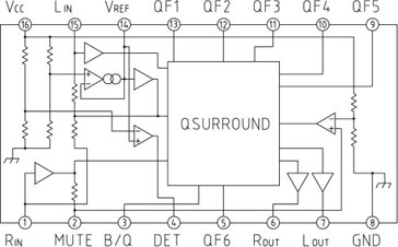
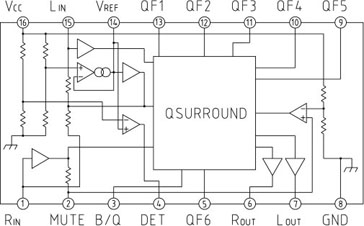
The internal structure of MM1454 is shown in Figure 1. 
Figure 1 MM1454 internal structure diagram
The MM1454 is available in a 16-pin SOP package. The pin functions are listed in the table.
The noise suppression signal of MM1454 is output to pin 4 (DTE pin), which can turn off the power supply of the power amplifier. Before turning off the power of the IC, by turning off the power amplifier connected to the last stage inside the IC, the noise during the voltage drop of the power supply can be suppressed or even eliminated.
MM1454 has a wide range of applications in TVs, stereos and active speakers. Figure 2 shows its typical application circuit, the power supply current ICC = 16mA, the output noise voltage is typically 15μVrms, the typical total harmonic distortion rate THD≤0.1%, the voltage gain is typically 10.5dB (VIN = 0.75Vrms, f = 1KHz, SW1 turns on contact B).
In Figure 2, the input signal of the left / right two channels with a typical value of 0.75Vrms comes from the output of the pre-amplifier in the previous stage. The two output signals on pin 6 and pin 7 of MM1454 are sent to the next-stage audio power amplifier circuit through a 22μF Coupling capacitor. Connect a 100μF smoothing capacitor and a 0.1μF bypass capacitor between the 9V power supply voltage Vcc and ground. When the switch SW1 on pin 3 is grounded (connecting contact B), it is in bypass mode; when SW1 is connected to a 5V power supply (connecting contact A), it is in Q Surround mode. In Q Surround mode, a current of about 350μA flows into pin 3. The squelch suppression signal is connected to pin 4 to turn off the power supply of the power amplifier. The 10μF capacitor connected between pin 2 and ground can reduce the noise when the power is turned on. The tolerance of the external filter resistors for pins 5 and 9 to 13 is ± 1%, and the capacitor tolerance is ± 5%.
Table 1 MM1454 pin functions
Pin | symbol | Features |
1 | RIN | Left channel input |
2 | MUTE | Squelch suppression |
3 | B / Q | Q SUurround bypass |
4 | DET | Vcc shutdown detection |
5 | QF6 | (Qf1-Qf6) filter pin |
FFFFFF | QF5 | |
10 | QF4 | |
11 | QF3 | |
12 | QF2 | |
13 | QF1 | |
6 | ROUT | Right channel output |
7 | LOUT | Left channel output |
8 | GND | Ground |
14 | VREF | Reference voltage |
15 | LIN | Left channel input |
16 | Vcc | voltage |

Figure 2 Typical application circuit of MM1454
Special equipment for university physics laboratory
Teaching Equipment,Optical Bench Kit,Optical Instruments In Physics,Electrooptical Modulator Experimental Instrument
Yuheng Optics Co., Ltd.(Changchun) , https://www.yuhengcoder.com