1. Ground loop problem and ground potential difference in signal transmission
There are many reasons why a ground loop can occur in the meter circuit. When the signal transmission and receiving devices are connected to different grounding points or different power sources, a ground loop will occur, which is common in long-distance cable transmission. They may also be due to physical contact between the metal casing of the device and the ground. The ground loop caused an unobserved electrical circuit, creating an error source.
Since the accuracy of the signal cannot be measured by simple observation at the receiving end of the signal, the ground loop generated by the different ground potentials introduces an undetectable error into the signal loop.
In two-wire signal transmission without signal isolation, there are signal error problems caused by these ground loops.
In some cases, signals such as lightning and surges are loaded on the signal line with long lines, damaging the modulation or detection devices on the port.
In the other case, the ground potential of the port reference of the two devices is different, which may cause the port voltage to exceed the standard and damage the device port.
Second, non-isolated two-wire signal transmission

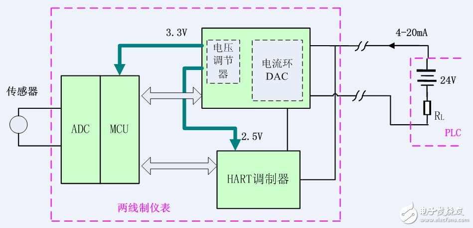
Figure 1
In the circuit of Figure 1, the signal of the sensor is converted into a digital signal by the ADC, and then sent to the current loop DAC and the HART modulator through the MCU to form a 4-20 mA signal output. The current loop DAC is taken from the 4-20 mA bus output of the PLC. The power supply, through the built-in voltage regulator output 3.3V and 2.5V, provides a small amount of power to the MCU and HART modulator.
In the transmission mode of Figure 1, there is a potential difference between the two-wire meter and the grounding potential of the remote PLC, which introduces common mode interference, which causes the transmission error of the 4-20 mA signal and also affects the normal communication of the HART bus. If the common mode interference is too large (beyond the allowable range of the common-mode voltage of the internal device), even the device inside the two-wire meter is damaged.
Third, isolation two-wire system signal transmission

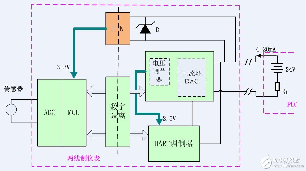
Figure II
Based on the above-mentioned hidden dangers due to different ground potentials, the MCU can be isolated from the current loop DAC and HART modulator by digital isolation. The current loop DAC and HART modulator are in floating form, making the two-wire instrument and PLC system A high impedance is formed between the two ground potentials, reducing the loop current between the ground lines, forming electrical isolation between the two devices, thereby reducing the transmission error of the 4-20 mA signal while eliminating the hidden danger of common mode interference.
Because the two-wire meter has no additional power supply port, its power is supplied through the 4-20mA loop. With this isolation, the 2.5V power supply of the HART modulator is still obtained from the voltage regulator built into the current loop DAC. The 3.3V power supply of the MCU system becomes a problem. A better solution is to connect a Zener diode in series in the 4-20mA circuit as shown in Figure 2. Then use the HK module of Guangzhou Jinshengyang Technology Co., Ltd. to isolate the output 3.3V and supply power to the MCU system.
In this way, the use of Jin Shengyang's HK module and digital isolation circuit can realize the electrical isolation between the two-wire instrument and the PLC system, avoiding the system measurement error and equipment damage caused by the ground potential, and further improving the reliability of the system.
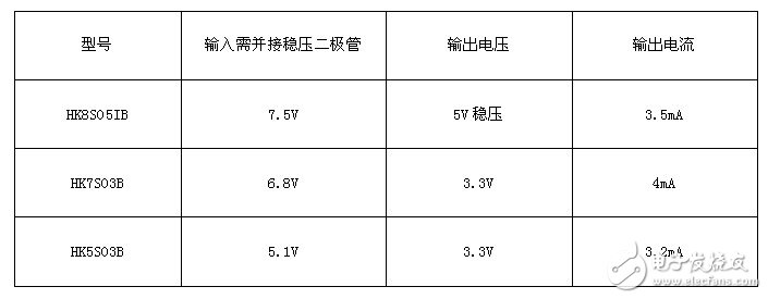
The optional Jinshengyang HK module models are as follows:

In general, the higher the diode regulation value of the parallel connection of the input of the HK module, the greater the output power that HK can provide. In order to maximize the transmission distance of the two-wire signal, under the premise of meeting the power consumption of the MCU, try to select a Zener diode with a lower regulation value as the input voltage of the HK module. For the input voltage not listed in the list, you can order it to Guangzhou Jinshengyang Technology Co., Ltd.
Fourth, summary
The HK module of Guangzhou Jinshengyang Technology Co., Ltd. can realize the isolated transmission of the two-wire signal, eliminate the error caused by the difference of the ground potential and the possible impact of the common mode signal on the port device, and provide the signal transmission mode for the industrial control site. A new and better choice.
Of course, for non-isolated applications, such as MCU requires a slightly higher operating frequency, and the current loop DAC chip can not provide enough energy, you can also consider using a power-taking circuit similar to Figure 2 to provide additional energy, this article will not repeat .
The Tianjin online power take-off module of Guangzhou Jinshengyang Technology Co., Ltd. has further innovated on the basis of the patented circuit in 2012, which improves the power conversion efficiency of the HK module. It is believed that it can meet the higher power requirements of the two-wire meter.
Lan Transformers For Automotive Battery,Ferrite Core Lan Transformer,Ethernet Isolation Transformer,Pulse Ethernet Transformer
IHUA INDUSTRIES CO.,LTD. , https://www.ihua-magnetics.com