1. Summary
The power factor correction circuit shapes the input current waveform of the off-line power source to maximize the active power drawn from the power source. Ideally, the appliance should behave as a purely resistive load, at which point the reflected power absorbed by the appliance is zero. In this case, there is essentially no input current harmonics. The current is a perfect replica of the input voltage (usually a sine wave) and is in phase with it. In this case, the current absorbed from the mains power supply is minimized for the active power required to perform the required work, and the losses and costs associated with the distribution equipment and associated equipment in the associated process are also reduced. Since there are no harmonics, interference with other devices that use the same power supply is also reduced. Another reason for the use of PFC in many power supplies today is to meet regulatory requirements. Electrical equipment in Europe must now comply with the European specification EN61000−3−2. This requirement applies to most appliances with an input power of 75 W or more, and it specifies the maximum amplitude of the power frequency harmonics including up to 39 harmonics. Although the United States has not yet made such a request, power supply manufacturers who want to sell products worldwide are designing products that meet this requirement.
definition
Power factor correction can be simply defined as the ratio of active power to apparent power, ie:

The active power is the average of the product of the current and voltage instantaneous values ​​in one cycle, and the apparent power is the product of the rms value of the current and the rms value of the voltage. If the current and voltage are sinusoidal and in phase, the power factor is 1.0. If the two are sinusoidal but different phases, the power factor is the cosine of the phase angle. In electricity
In the basic course of the work, the power factor is often defined as such, but it is only applicable to the specific case where the current and voltage are pure sine waves. This happens when the load consists of resistors, capacitors, and inductive components, all of which are linear (not subject to current and voltage variations).
Switch mode power supplies exhibit a nonlinear impedance to the grid supply due to the input circuit. The input circuit usually consists of a half-wave or full-wave rectifier followed by a storage capacitor that maintains the voltage close to the peak value of the input sine wave until the next peak arrives.
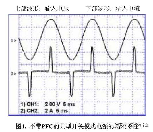
Charging. In this case, the current is only drawn from the input at each peak of the input waveform, and the current pulse must contain enough energy to maintain the load voltage before the next peak arrives. This process involves injecting a large amount of charge into the capacitor in a short time and then slowly placing it on the load by the capacitor.
This is done by electricity, and then this cycle is repeated. It is quite common for current pulses to be 10% to 20% of the period, which means that the pulse current should be 5 to 10 times the average current. Figure 1 depicts this situation.

Please note that although the current waveform is severely distorted, the current and voltage can be completely in phase. Applying the definition of "phase angle cosine" will give the wrong conclusion that the power factor of the power supply is 1.0.
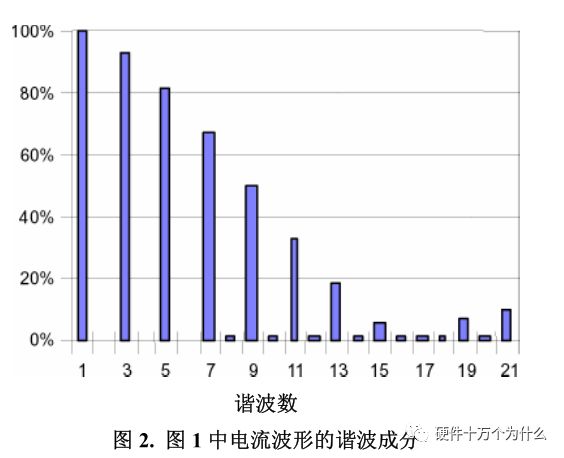
Figure 2 shows the harmonic content of the current waveform. The fundamental (60 Hz in this example) is shown with a 100% reference amplitude, while the amplitude of the higher harmonics is shown as a percentage of the fundamental amplitude. Note that there are almost no even harmonics, which is the result of waveform symmetry. If the waveform contains infinitely narrow and infinitely high pulses (mathematically
Called the δ function, the spectrum will flatten, which means that all harmonics have the same amplitude. By the way, the power factor of this power supply is about 0.6.

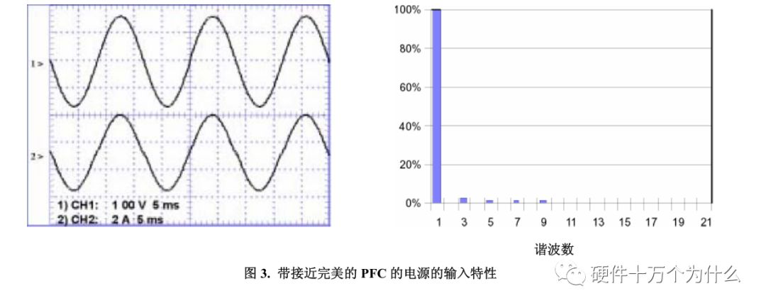
For reference, Figure 3 shows the power factor corrected power input. Its current and voltage waveforms are very similar in shape and phase. Note that its input current harmonics are almost zero.

Power factor correction and harmonic reduction
It can be clearly seen from the foregoing description that the high power factor and the low harmonic are consistent. However, there is no direct relationship between them, and the relationship between total harmonic distortion and power factor is reflected in the following equation.
THD means: harmonic distortion. Harmonic distortion is the harmonic component of the output signal that is more than the input signal. Harmonic distortion is caused by the system not being completely linear. The sum of all additional harmonic levels is called total harmonic distortion:

Where Kd is the distortion factor and is equal to:

Therefore, when the fundamental component of the input current and the input voltage are in phase, Kθ = 1, and:

As mentioned earlier, even a perfect sinusoidal current, as long as its phase and voltage are inconsistent, will result in a poor power factor.
Then, the relationship between power factor and harmonic distortion is obtained:

It follows that 10% THD corresponds to a power factor approximately equal to 0.995. Obviously, setting the limit for each harmonic can better accomplish the task of controlling the "contamination" of the input current, either from the point of minimizing current or reducing interference from other devices. Although this process of shaping the input current is often referred to as power factor correction, in international specifications, the success of the shaping is usually measured in terms of harmonic content.
Type of power factor correction
The input characteristics shown in Figure 3 are obtained by "active" power factor correction. The switch mode boost converter is placed between the input rectifier and the storage capacitor. The converter is controlled by a more complex IC. Its additional circuit can The input current is shaped to match the waveform of the input voltage. This is the most commonly used PFC type in today's power supplies. But it is not the only type. There is no rule that the PFC must be made up of active circuits (transistors, ICs, etc.). Any method that can make harmonics below the specification limits is allowed.
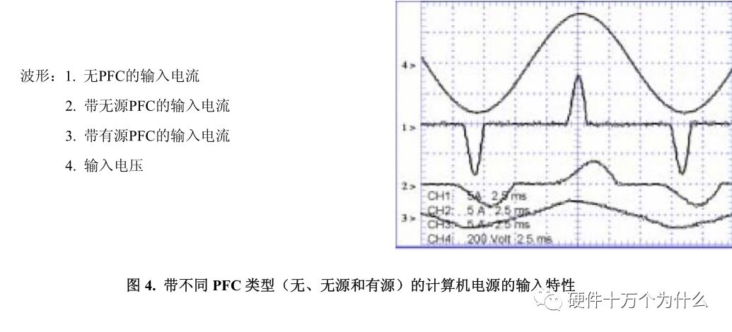
The results show that placing the inductor at the same position as the active circuit can also achieve the purpose of limiting harmonics. A large enough inductance reduces the peak current and broadens the current waveform over time to reduce harmonics to conform to specifications. This approach has been used in some desktop PC power supplies, with inductor sizes (approximately 50 mm 3 ) and their weight (core and copper windings) acceptable. In the case where the power level exceeds the typical personal computer power (250 W), this passive method is rarely used due to size and weight limitations. Figure 4 shows the inputs for three different 250W computer power supplies.
Characteristic, all current waveforms have the same scale factor.

Travel Charger Adapter is convenience for these people who always travel in many countries. Desktop Power Adapter have normal DC connector for your need, and wall power adapter have mutil plug, like US/UK/AU/EU etc. We also can produce the item according to your specific requirement. The material of this product is PC+ABS. All condition of our product is 100% brand new.
Our products built with input/output overvoltage protection, input/output overcurrent protection, over temperature protection, over power protection and short circuit protection. You can send more details of this product, so that we can offer best service to you!
Travel Charger Adapter,Portable Travel Charger Adapter,Mini Travel Charger Adapter,Travel Charger Supply
Shenzhen Waweis Technology Co., Ltd. , https://www.laptopsasdapter.com