As an applications engineer, I was often asked questions about the no-load operation of the regulator. Most modern LDOs and switching regulators can work stably under no-load conditions. So why do people ask again? Some older power devices require minimal load to ensure stability because one of the electrodes that must be compensated is affected by the effective load resistance. For example, Figure A shows that the LM1117 requires at least 1.7 mA of load current (5 mA max).

Figure A. LM1117 minimum load current specification.
Most new devices can work without load, and there are few exceptions to this rule. Some design techniques allow LDOs to remain stable with any output capacitor (especially low ESR capacitors). They are also used to guarantee device stability under no-load conditions. For a few modern devices that require a load, this limitation is generally caused by the leakage current of the bypass element, not the cause of stability. So how do you tell? Please refer to the data sheet. If the device requires a minimum load, the data sheet must provide some information. The ADP1740 and other low-voltage, high-current LDOs fall into this category. In the worst case, the integrated power switch generates approximately 100 μA (85°C) and 500 μA (125°C) of leakage current. Under no-load conditions, the leakage current charges the output capacitor until the VDS of the switch is low enough to reduce the leakage current to a negligible level while increasing the no-load output voltage. The data sheet indicates that a minimum load of 500 μA is required. Therefore, if the device is to operate at high temperatures, it is recommended to use a simulated load. The load is less than the device's rating of 2 A. Figure B shows the minimum load current specifications listed in the ADP1740 data sheet.
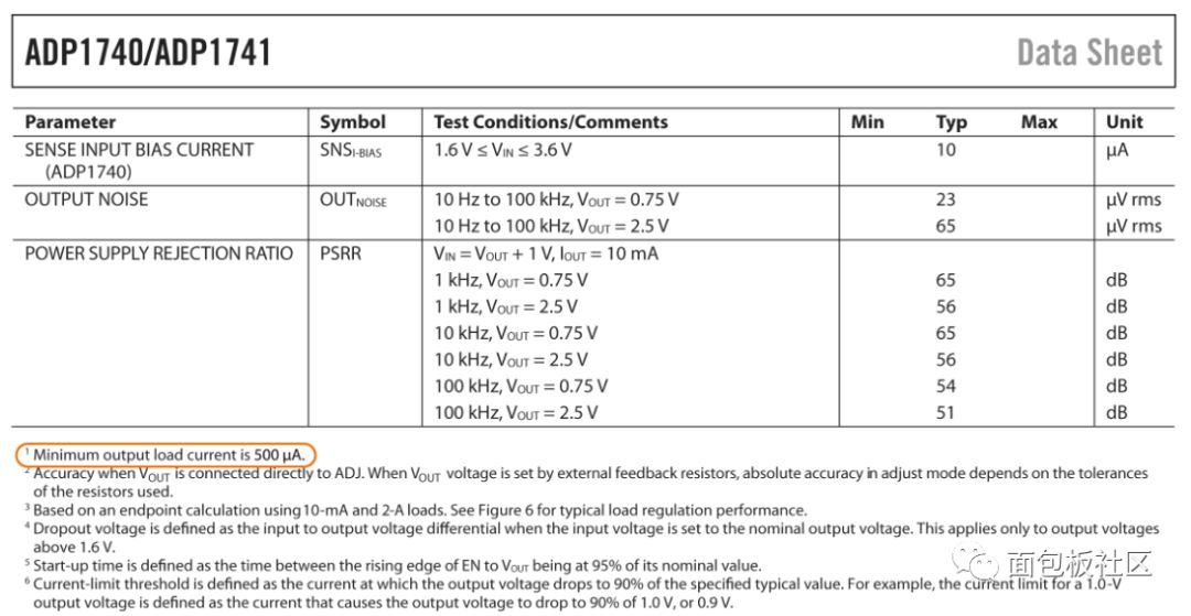
Figure B. ADP1740 minimum load current specification.
What if the data sheet does not explicitly indicate the minimum load? In most cases, no minimum load is required. Although it may not sound convincing, if the minimum load is required, this information will certainly be provided in the data sheet. However, the confusion often comes along because the datasheet usually uses charts to show the specifications of a certain scope of work. Most of these charts are logarithmic, which allows them to display decades of load range, but the logarithmic scale cannot be zeroed. Figure C shows the ADM7160's output voltage and ground current and load current in the 10 μA to 200 mA range. Other diagrams, such as ground current and input voltage, show the measurement results for multiple load currents, but do not show data at zero current. In addition, parameters such as PSRR, supply voltage regulation, load regulation, and noise specify a certain load current range that does not include zero, as shown in Figure D. However, this does not mean that the minimum load is required.
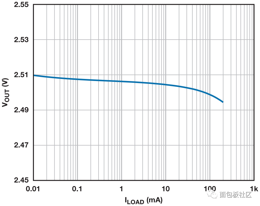
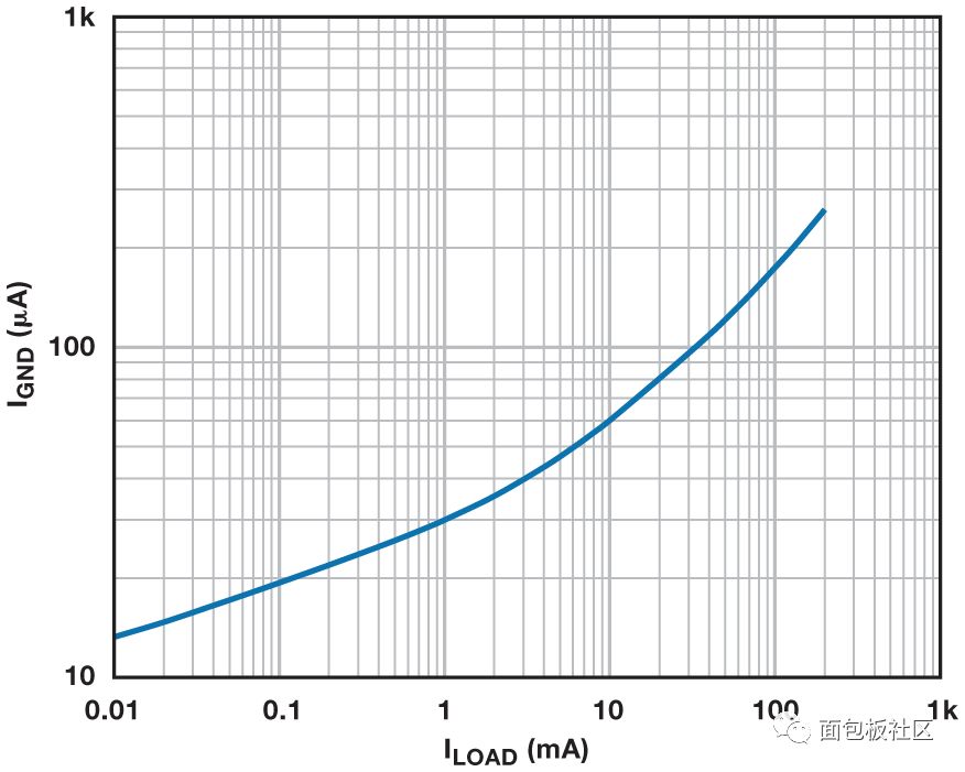
Figure C. ADM7160 Output Voltage and Ground and Load Currents.

Figure D. ADM7160 load adjustment.
If a user uses a switching regulator with Power Save Mode (PSM), he or she will often be concerned about how the regulator will operate at light loads, because the PSM will reduce the operating frequency, skip the pulse, provide a burst or some of these conditions. Combinations. At light loads, PSM reduces power consumption and improves efficiency. The disadvantage is that the output ripple increases significantly, but the device remains stable and can easily operate without load. As shown in Figure E, the ADP2370 high voltage, low quiescent current buck regulator produces more ripple due to PSM operation when the load is switched between 800 mA and 1 mA. The fact that the test is completed at 1 mA does not mean that 1 mA is the minimum load.
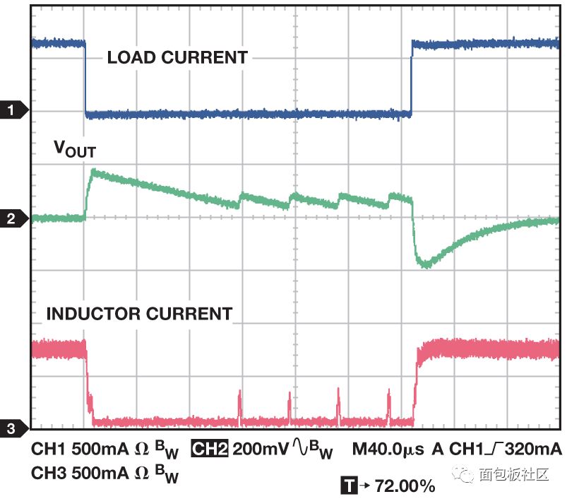
Figure E. ADP2370 load transients in power save mode. Figure F shows the ripple voltage as a function of load current. In this example, the ripple voltage shown in the figure has been reduced to zero, indicating that the load can be zero and the no-load noise is no worse than the noise at 1 mA or 10 mA.
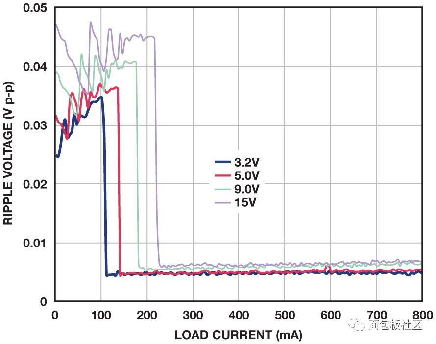
Figure F. ADP2370 Output Ripple and Load Current. Conclusion Most modern regulators can operate stably with zero load current. If in doubt, refer to the data sheet. In spite of this, we must pay attention. The logarithmic plot cannot be zeroed, and the test is not always performed at zero load current. Therefore, although no-load data is not shown, you should not infer that the regulator cannot operate normally under no-load conditions. When using a switching regulator, the ripple in the power saving mode is normal and does not mean that it is unstable.
400W Solar Panel,Residential Solar Panel Kits,Solar Panel System,320W Solar Panel
Jiangsu Stark New Energy Co.,Ltd , https://www.stark-newenergy.com