[Introduction] This article mainly talks about the 3V-5V level conversion circuit diagram, let's learn together.
Keywords: level-shifting triode This article mainly talks about the 3V-5V level-shifting circuit diagram. Let's take a look at it:
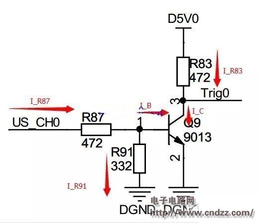
The left end of the figure is connected to the 3.3V CMOS level, which can be an IO port of STM32, FPGA, etc., and the output of the right end is 5V level, achieving conversion from 3.3V to 5V.
Now let's analyze the role of each resistor (the core idea of ​​grabbing is that the Vbe of the triode is constant at around 0.7V):
Assuming no R87, when the high level of US_CH0 is directly added to the BE of the triode, where is the voltage of 0.7V going?
Suppose there is no R91. When the state of US_CH0 is uncertain, the default is to output high or low level of Trig? Therefore, R91 functions as a fixed level. At the same time, if there is no R91, just turn on the triode by inputting “0.7Vâ€, the threshold voltage is too low, and R91 has the function of raising the threshold voltage (refer to the second section for the analysis of the buzzer).
3V-5V level conversion circuit diagram

However, if you add R91, you should pay attention to it: if R91 is too small, the base voltage is only about Vb"0.7V, so that US_CH0 can be turned on when it is high. Vb=1.36V in the above figure.
Suppose there is no R83. When the input US_CH0 is high (when the transistor is turned on), D5V0 (5V high level) is directly added to the CE level of the triode, and the CE and triode of the triode are easily damaged.
Further analysis of its working mechanism:
When the input is high, the transistor is turned on, and the output is clamped to the Vce of the triode. The test result for the circuit is only 0.1V.
When the input is low, the transistor is not conducting, and the output is equivalent to pulling up the input of the next-stage circuit using a 10K resistor. The actual test result is 5.0V (no-load).
Please note:
For high current loads, the characteristics of the above circuit will not perform so well, so it has been emphasized here - this circuit is only suitable for level shifting of loads from 10 mA to tens of mA
Anti-rat ant Solar Cable is a kind of cable specially used for photovoltaic power generation system, its main function is to prevent small animals such as mice and ants from destroying the photovoltaic line.
The characteristics of anti-rat ant solar cable are as follows:
1. Anti-ant performance: anti-rat ant solar cable adopts special materials and technology treatment, has strong anti-ant performance, and can effectively prevent the invasion of ants and other small animals.
2. Anti-bite performance: anti-rat ant solar cable has good anti-bite performance, can resist the bite of mice and other animals, to avoid short circuit, fire and other safety hazards.
3. Weather resistance: anti-rat ant solar cable is made of high-quality materials, has good weather resistance, and can run stably for a long time under various harsh environmental conditions.
4. Easy installation: The installation method of anti-rat ant solar cable is the same as that of ordinary light cable, without additional tools and equipment, easy and quick installation.
5. Efficient performance: anti-rat ant solar cable has low resistance and high conductivity, which can ensure the efficient operation of photovoltaic system.
In short, the anti-rat ant solar cable is a kind of cable specially designed for photovoltaic power generation system, with the characteristics of ant-proof, anti-bite, weather resistance, easy installation and efficient performance, which can effectively protect the solar cable from the damage of small animals such as mice and ants.
Anti-Mouse Ants Solar Cable,Adapter Cable,Ant Rat Resistant Solar Cable,Ant Resistant Dc Cable
Suzhou Yonghao Cable Co.,Ltd. , https://www.yonghaocable.com