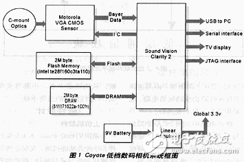
Digital cameras can be designed with the Motorola VGA CMOS sensor. Figure 1 shows a block diagram of a Coyote low-end digital camera system. This digital camera system consists of the following components: "C" frame lens; VGA CMOS sensor; full view Clarity 2.0 ASIC; 2 Mbyte flash memory; 2 Mbyte SDRAM; The five main parts of the Coyote camera are described below.
"C" frame lens
The Coyote low-end digital camera system has the ability to use 8mm, 12mm and "C" frame lenses. The lens can be mounted in the camera by bolting one of three different lens mounts to the main printed circuit board. This design uses a "C" frame lens. If you need 8mm and 12mm lenses, please contact the company. The recommended lens performance indicators are shown in Table 1.
Table 1 lens performance indicators

VGA CMOS sensor and full-view Clarity 2.0 ASIC
The CMOS VGA Image Sensor (MCM20014) is a fully integrated, high performance CMOS image sensor with integrated timing, control and analog signal processing for digital imaging applications. This device provides designers with a complete single-chip image capture and processing engine imaging solution that makes it a true "on-chip camera."
The complete view Clarity 2.0 ASIC provides a set of advanced software hardware for the development of digital cameras or imaging systems.
The VGA CMOS image transmitter and Clarity 2 ASIC form the backbone of the Coyote digital camera.

The following describes the work of the Coyote digital camera.
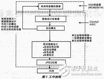
The Coyote digital camera (when first turned on and during idle or click-click time) continuously takes a sample image from the sensor at a frame rate of 12 fps. The software uses these sub-images to collect images and statistics in the environment. Based on the analysis of these statistics, the autoexposure software algorithm calculates the exposure time to get the best image (the workflow is shown in Figure 2). The exposure time is then written to the sensor's integration time register. In order to maintain proper exposure, these values ​​are often read and written back to the sensor through the I2C interface.
Automatic white compensation and total gain are completely implemented in software. However, white compensation and total gain can also be achieved by writing values ​​to the sensor color gain register and the total gain register.
When you press the camera's photo button, the camera captures a single full-sample image. The software then processes the images, compresses them, and stores them in flash memory.
The sensing operating frequency used in the Coyote digital camera is 9.75 MHz.
2M byte flash
2M bytes of flash memory or 16M bits (1M & TImes; 16) NVRAM (non-volatile RAM) are required in Coyote digital cameras. This particular flash memory can be configured as 16-bit 1024K words or 8-bit 2048K bytes.
2M byte SDRAM
Coyote digital cameras require 2M bytes of SDRAM or a CMOS 16M (2&TImes; 512 & TImes; 16) synchronous DRAM (2K refresh cycle).
power supply
Power the system with a 9V power supply. The system uses a linear regulator to provide a 3.1V to 3.8V@~250mA power supply.
firmware
The Coyote digital camera has been mentioned to perform certain post-sensors (software is part of the firmware available for the Clarity 2 ASIC. However, the firmware/software is not only responsible for image statistics acquisition and image processing algorithms, but also for the implementation of the Coyote camera software driver. .
Although the Clarity 2 ASIC has many drivers available, the drives used in Coyote cameras are:
1) Sensor interface driver
2) NTSC driver
3) USB drive
4) Flash interface driver
5) I2C driver
6) Button driver
Custom firmware for use in low-end digital cameras comes from Sound Vision Inc.

How to view stored images
There are two ways to view images stored in a Coyote digital camera: with a PC and a TV monitor.
Viewing stored images with a PC
Users can download images stored in the Coyote camera's flash memory to a PC for viewing using a variety of commercial and custom software.
Watching stored images with a TV monitor
A still image of the digital camera can be viewed on the NTSC monitor via a small micro-stereo connector (next to the system). The video is compatible with NTSC or PAL. A 75Ω cable is required to connect to the TV monitor.
Home Audio Speaker,10 Woofer Speaker,10 Inch Woofer Speaker,Portable Woofer Speaker
Guangzhou Yuehang Audio Technology Co., Ltd , https://www.yhspeakers.com