1. Introduction With the development of the communication industry, the field of mobile communication applications continues to expand, and the design of mobile terminals has gradually attracted much attention. This article introduces in detail the GSM module TC35 from Siemens, the level shift chip MAX3238 from TI, and other devices, as well as the hardware circuit of the mobile terminal. The design can complete short message sending and receiving, voice transmission, data transmission with PC and other functions, and has been applied in GPS vehicle monitoring system based on GSM short message.
2. TC35 module TC35 is a new generation wireless communication GSM module launched by Siemens, which can quickly, safely and reliably implement data, voice transmission, short message service (Short Message Service) and fax in the system solution. The working voltage of the module is 3.3-5.5V, it can work in two frequency bands of 900MHz and 1800MHz, and the power consumption of the frequency band is 2W (900M) and 1W (1800M) respectively. The module has an AT command set interface, which supports text and PDU mode short messages, the third group of Type 2 faxes, and non-transparent modes of 2.4k, 4.8k, and 9.6k. In addition, the module also has a phone book function, multi-party calls, roaming detection function, common working modes are power saving mode, IDLE, TALK and other modes. Through the unique 40-pin ZIF connector, the two-way transmission of power connection, command, data, voice signal and control signal is realized. Through the ZIF connector and the 50Ω antenna connector, the SIM card holder and the antenna can be connected separately.
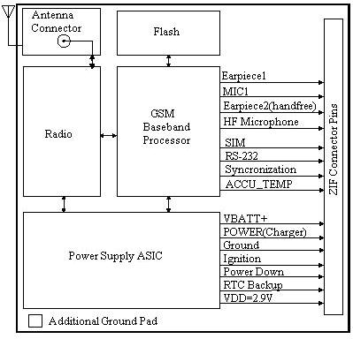
The TC35 module is mainly composed of six parts: GSM baseband processor, GSM radio frequency module, power supply module (ASIC), flash memory, ZIF connector, and antenna interface. As the core of TC35, the baseband processor mainly processes voice and data signals in GSM terminals, and covers all analog and digital functions in cellular radio frequency equipment. Without the need for additional hardware circuits, it can support FR, HR and EFR voice channel coding.
 Figure 1 TC35 functional block diagram
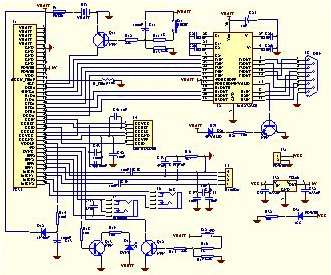
3. Peripheral application circuit The normal operation of the TC35 module requires the corresponding peripheral circuit to cooperate with it. The TC35 has a total of 40 pins, which are connected to the power circuit, startup and shutdown circuit, data communication circuit, voice communication circuit, SIM card circuit, indicator light circuit, etc. through the ZIF connector. as shown in picture 2,
 Figure 2 TC35 peripheral circuit connection
3.1 Power supply and start-up circuit The power supply circuit is divided into two parts: a rechargeable battery and a regulated power supply module: the rechargeable battery mainly provides the entire system with a 3.6V working voltage and generates the high level required by MAX3238; TI's three-terminal power supply module UA7806 Convert the external + 12V DC power supply to + 6V, and connect it to the 11 and 12 pins of the ZIF connector. In the charging mode, provide the TC35 with a + 6V, 500mA charging voltage.
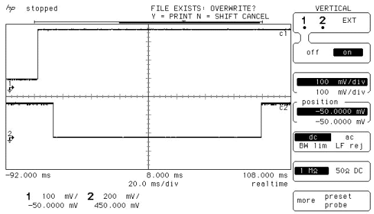
The startup circuit consists of an open-drain transistor and a power-on reset circuit. After the module is powered on for 10ms (the battery voltage must be greater than 3V), in order to make it work properly, a low-level signal with a duration of at least 100ms must be added to pin 15 (/ IGT), and the falling time of the signal is less than 1ms. After starting, the 15-pin signal should remain high. As shown in the figure below, the signal generated by the startup circuit can be seen from the delay of 10ms and the low level of 100ms.
 Figure 3 The falling edge of the start signal collected
3.2 Data communication circuit Data communication circuit mainly completes short message sending and receiving, communication with PC, software flow control and other functions. The data interface of TC35 adopts serial asynchronous transceiver, which complies with the ITU-T RS-232 interface circuit standard, and works at CMOS level (2.65V). The data interface is configured with 8 data bits, 1 stop bit, and no parity bit. It can operate at a baud rate of 300bps to 115kbps, and the supported automatic baud rate is 4.8kbps to 115kbps (except 14.4kbps and 28.8kbps) . The TC35 module also supports RTS0 / CTS0 hardware handshake and XON / XOFF software flow control.
The data communication circuit takes TI's MAX3238 chip as the core, and realizes level conversion and serial communication functions.
The power supply voltage of TI's MAX3238 chip is 3 ~ 5.5V, which complies with TIA / EIA-232-F and ITU v.28 standards. It has unique ± 15KV human body electrostatic protection measures, is compatible with 5V logic input, contains 3 receive and 5 send serial communication interfaces, and the maximum data transmission rate can reach 250 kbps. The biggest feature of this chip is that when there is no data input in the serial port, the power management can be flexibly performed. That is, when FORCEON (pin 13) is low and / FORCEOFF (pin 14) is high, Auto- Powerdown Plus function is effective. In the normal operation mode, if the chip does not detect a valid signal at the receiving and transmitting pins within about 30 seconds, it will automatically enter the Powerdown mode, which consumes 1uA of power. If the FORCEON and / FORCEOFF pins are both high, the Auto-Powerdown Plus function is disabled. When the Auto-Powerdown Plus function is valid, if a signal input is detected on the receive or transmit pin, the chip is automatically activated and transitions to the normal working state. If the input voltage of any receiving channel is higher than 2.7V or less than -2.7V, or the time between -0.3V and 0.3V is less than 30uS, the / INVALID (15-pin) pin is high (data is valid). If the input voltage of all receiving channels is between -0.3V and 0.3V for more than 30uS, the / INVALID (15-pin) pin is low (data is invalid).
| FORCEON | / FORCEOFF | Auto-PowerdownPlus | OPERATION STATUS | T_OUT | R_OUT | R1OUTB |
| × | 0 | × | Powerdown (Forced Off) | High-Z | High-Z | Active |
| 1 | 1 | × | Normal Operation (Forced On) | Active | Active | Active |
| 0 | 1 | <30s | Normal Operation (Auto-Powerdown Plus) | Active | Active | Active |
| 0 | 1 | > 30s | Powerdown (Auto-Powerdown Plus) | Active | Active | Active |
The above characteristics of the chip meet the requirements of TC35 as a 3-terminal receiving and 5-channel transmitting circuit connection for mobile terminals. When the MAX3238 is connected to the corresponding pin of the ZIF connector, pay attention to the correct connection of the sending and receiving pins. MAX3238 also needs to connect four 0.1uF capacitors to complete the level conversion function. The signals output by the TC35 module through the RS-232 interface pins are RxD0, CTS0, DSR0, DCD0, and RING0. The input signals are TxD0, RTS0, and DTR0.
Because the interface circuit of TC35 uses all the pins of the 9-pin serial port, TC35 can obtain DTR0, DSR0, DCD0 and RING0 control signals. The signal RING0 is used to indicate to the cellular device that the Unsolicited Result Code (URC) is received. Through AT command, you can set different operation modes of TC35.
3.3 Voice communication circuit Because TC35's GSM baseband processor integrates audio filtering, ADC, DAC, voice synthesis and other parts, the peripheral circuit connection of the module's voice interface is relatively simple. TC35 has two voice interfaces, each interface has analog microphone input and analog headset output. In order to suit different peripherals, the module has 6 voice modes, which can be selected by the command AT ^ SNFS. The default configuration of the first voice interface is the Votronic HH-SI-30.3 / V1.1 / 0 handheld microphone. The voice modes are 1 (default), 4, and 5, with mode 1 parameters fixed. The second voice interface is set for headphones and microphone, and the voice mode is 2, 3, 6.
In order to prevent the introduction of high-frequency interference from the microphone and headphone wires, affecting the normal operation of the TC35. When designing the circuit, inductances are connected to the jacks of the microphone, earphone, and handheld earpiece. In addition, considering the static electricity protection factor, all voice signal input terminals are coupled to GND through capacitors.
3.4 The SIM card circuit baseband processor integrates a SIM interface compatible with the ISO 7816-3 IC Card standard. In order to fit the external SIM interface, this interface is connected to the main interface (ZIF connector). On the basis of GSM11.11 reserves 5 pins for the SIM card, TC35 reserves 6 pins for the SIM card interface on the ZIF connector, the added CCIN pin is used to detect whether the SIM card holder is inserted There is a SIM card. When the SIM card is inserted, this pin is set to high level, the system can enter the normal working state. However, none of the SIM cards provided by mobile operators currently have CCIN pins, so connect the pins CCIN and CCVCC when designing the circuit.
When wiring the SIM card in the design, I found a problem worthy of attention: if the fourth pin CCGND of the SIM card is directly connected to the GND of the printed circuit board without any signal isolation protection, the volume during the call is very small. Taking into account factors such as electromagnetic compatibility and electrostatic protection in the design, in order to achieve the best call effect, a layer of copper isolation net is laid under the SIM bracket, that is, the top layer of the printed circuit board. The pins are connected, and the CCGND and the GND of the circuit board are coupled through two parallel capacitors and inductors. This action constitutes an isolation ground for the SIM card, shielding the interference of other signal lines to the SIM card. When you make a voice call again, the voice is clear.
4. Concluding remarks The mobile terminal composed of Siemens' GSM module TC35 and its peripheral circuits can accomplish short message transmission, data and voice communication well. The mobile terminal is combined with Rockwell's Jupiter GPS OEM board and is a vehicle-mounted mobile unit controlled by a single-chip computer. It can complete the work of transmitting vehicle positioning information using GSM short messages.
When people search gaming laptop, indicates that they need high performance 15 Inch Gaming Laptop, comes with big screen size, high cpu, large memory and storage, high resolution display, quality bigger 12000mAh battery, 2MP Camera, etc. 15 or 14 inch 500 Dollar Gaming Laptop, 10th generation laptop, 11th gen gaming laptop, 12th generation laptop, Laptop Intel Core I7, Intel I5 Laptop are the Top 10 Gaming Laptops. Every gamer want to buy Gaming Laptop with higher processors, big 8GB, 12GB, 16GB system memory ram, large Solid State Drive so that can handle or storage digital data at a high speed, 1920*1080 Full HD Slimmer screen provides user stunning vivid visuals, fingerprint reader, backlight keyboard, etc.
Nowadays 11th Laptop is the most competitive cpu, cause performance is better than 10th, but price is nearly same; besides, Solid State Drive cost 512GB is the most welcome and competitive one.
Of course, You can also contact us directly and share your exact requirements, so that we can send the right and valuable information quickly.
Gaming Laptop,Top 10 Gaming Laptops,500 Dollar Gaming Laptop,15 Inch Gaming Laptop,Buy Gaming Laptop
Henan Shuyi Electronics Co., Ltd. , https://www.shuyioemminipc.com