Abstract: At present, the automation integration of industrial dust removal system is getting higher and higher. This project is a small industrial dust removal project, so SMART series SR20 is used as the controller. The communication between the touch screen and the PLC is realized through Ethernet, and the communication between the PLC and the inverter adopts the USS protocol. Through the touch screen to realize the monitoring and control of the system, including the valve system and the fan frequency conversion system.
1. Project introductionDue to the large amount of waste gas dust generated in industrial sites, filter cartridge dust collectors are used more and more widely in air treatment projects as high-efficiency purification equipment for filtering dust. The dust removal system consists of the following parts: filter cartridge dust collector, external fan, cyclone dust collector, piping system and electric control system. The main functions of the electronic control system are: fan frequency conversion control, pipeline air valve control and differential pressure cleaning system. Considering the simplicity of system control, SMART products of Siemens' new generation of small automation products are selected as the controller of the electronic control system.
2. Process principle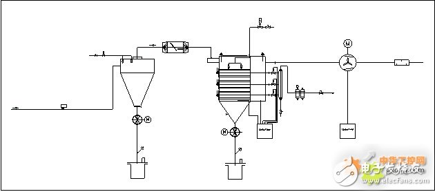
Figure 1 System block diagram
Figure 1 is a block diagram of the system. The system consists of the following parts: cyclone dust collector, filter cartridge dust collector, dust removal fan, piping system, frequency conversion control system and online pressure difference back-blowing system. The air containing dust particles generated at the production site of the factory is filtered by a cyclone dust collector and a filter cartridge dust collector to achieve a purification effect, and the purification efficiency is as high as 99%. The power of the dust removal fan is 75kW, and the corresponding Siemens MM430 frequency converter is selected as its frequency conversion speed regulating device. The filter cartridge dust collector is equipped with an online pressure difference back-blowing system. When working for a certain period of time, the surface of the filter cartridge will absorb dust, causing the pressure difference to increase. At this time, the pressure difference back-blowing and cleaning system will automatically perform according to the preset limit. Clean the dust.
3. Scheme selection1) Overall selection
According to the actual needs of customers, the system is relatively simple and the cost is considered. So choose Siemens' small PLC and SMART LINE touch screen as the control scheme. The frequency converter selects Siemens fan and water pump type special frequency converter MM430 series, the partial principle diagram of the system is shown in Figure 2 and Figure 3.
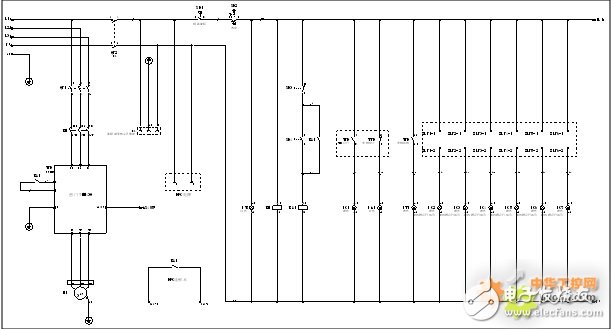
Figure 2 System schematic diagram (1)
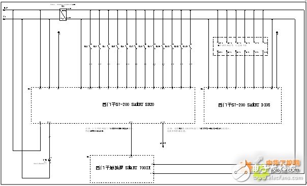
Figure 3 System schematic diagram (two)
2) List of electrical components
According to the system design requirements, the electrical components are selected. The list is shown in Table 1.

Table 1 List of electrical components
3) PLC I/O port description
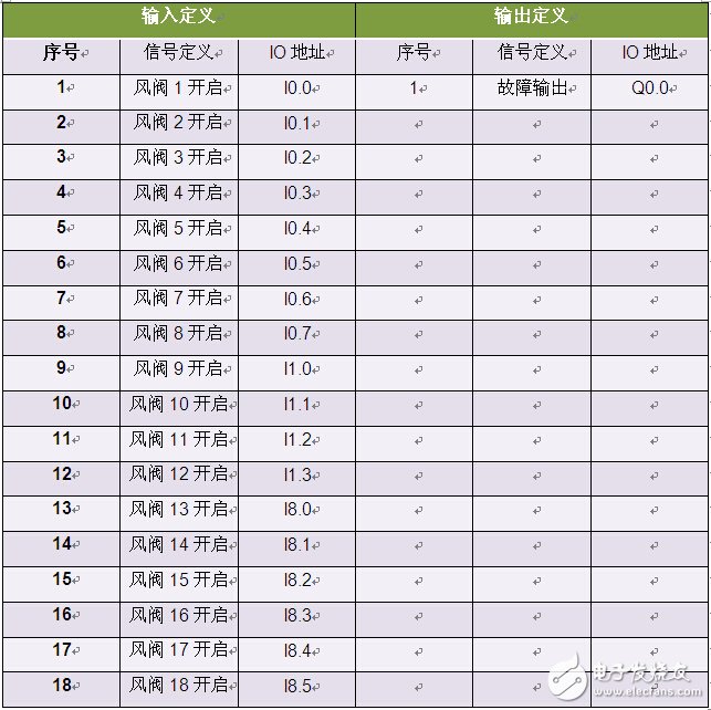
Table 2 Port definition
4) System communication The SMART PLC body has two communication ports, one Ethernet and one serial port. The communication between the PLC and the touch screen adopts Ethernet, and the PLC and the inverter adopt Siemens' special USS communication. In order to ensure the reliability and stability of communication, all communication connectors are dedicated connectors recommended by Siemens.
4. Equipment programming and debugging1) Program design ideas
Considering that the control process is relatively simple, the program for writing the program is mainly composed of three parts: the air valve detection module, the inverter USS communication module, and the time parameter module.
2) Detect 18-way electric valve
There are a total of 18 air valves working on site, which need to be detected by PLC, and when there are less than 11 air valves working, the system has an alarm output to prompt the user to open more air valves to ensure the stable operation of the dust removal system. Figure 4 is to detect one set of dampers, the other 17 are similar. Figure 5 shows the final statistics of the number of open dampers and alarms.
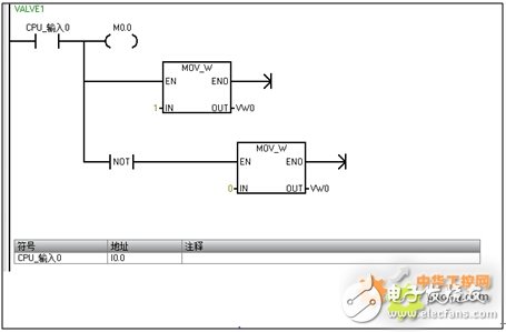
Figure 4 Detecting the first electric damper
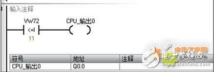
Figure 5 Statistics of the total number of dampers
3) USS communication between inverter and PLC
The frequency converter and SMART PLC adopt Siemens special-purpose USS communication, and the USS library function can be called directly in the programming software, which is simple and easy to use, as shown in Figure 6. In this program, the minimum frequency and maximum frequency are written to the inverter through USS, and the real-time operating frequency is observed through the touch screen. Figure 8 shows the lowest frequency input to the inverter through USS.
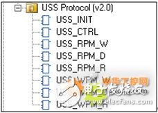
Figure 6 USS library
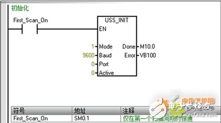
Figure 7 USS initialization
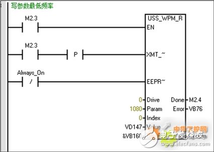
Figure 8 Write the lowest frequency of the inverter
4) Accumulated power-on time of the system
As shown in Figure 9, this program segment counts the accumulated working time of PLC power-on, and has a power-down retention function.
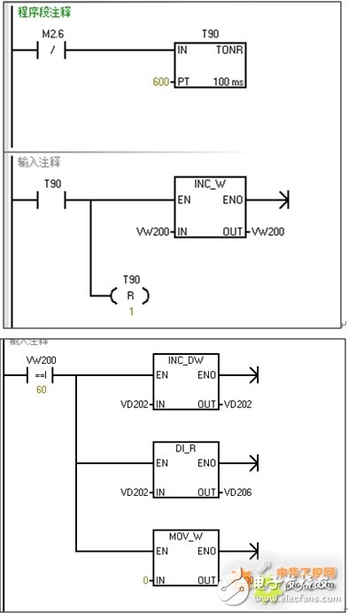
Figure 9 Statistic system accumulative power-on time
5) System man-machine interface
The man-machine interface adopts Siemens SMART LINE series simplified panel. In this project, a 7-inch panel with an Ethernet interface is used to communicate with SMART PLC through this interface. Figure 11 is one of its sub-screens, which monitors the working status of the electric damper of the system.
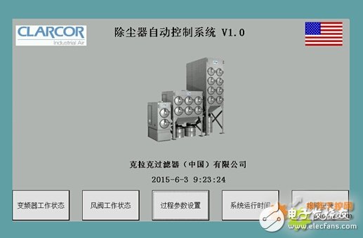
Figure 10 Boot interface
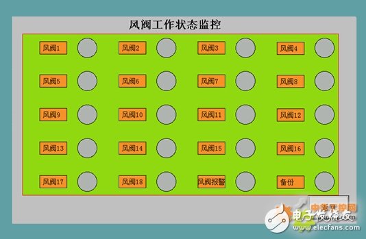
Figure 11 Damper monitoring interface
6) Control cabinet layout and on-site working status
Figure 12 to Figure 15 show the on-site working status and layout of the control cabinet.
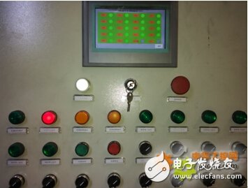
Figure 12 Control cabinet panel
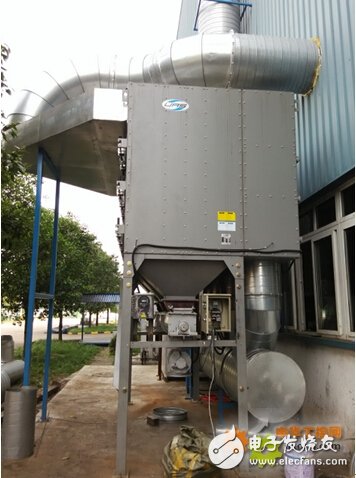
Figure 13 Equipment installation site
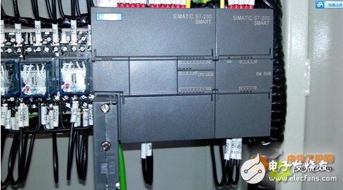
Figure 14 SMART PLC
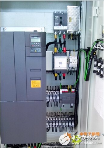
Figure 15 The internal layout of the control cabinet
5. Application experienceAs a new generation of Siemens S7-200 SMART in the field of small automation, it can meet the needs of small automation design. There are abundant expansion modules, which can be combined and matched according to system requirements. The programming method is completely transplanted to the S7-200CN series. For domestic customers who use the SMART series PLC, they can easily switch to this platform, and the programming software is more compact and requires low system resources. The programming interface uses the currently popular tiled menu. Keep up with the times. Another highlight of this PLC is that the body integrates an Ethernet interface. It is very easy to configure with the touch screen or to connect with the upper computer, and the communication speed is fast, without the need for a dedicated communication cable. It is hoped that Siemens can introduce more extensive expansion modules to enrich the current product line.
Aluminum Alloy LED lamps,Low Power LED lamps,LED line light
Kindwin Technology (H.K.) Limited , https://www.szktlled.com