This is a problem that has caused headaches for many people. Looking for information on the Internet is as follows. We need to know that copper foil thickness is 0.5 oz (about 18 μm), 1 oz (about 35 μm), 2 oz (about 70 μm) copper, 3 oz (about 105 μm) and more.
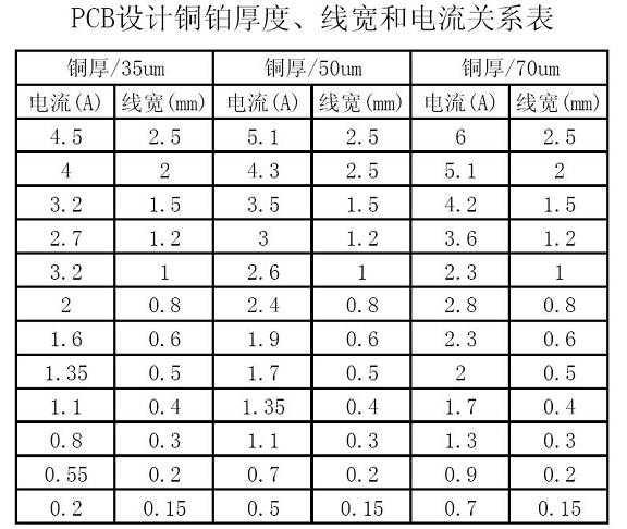
1. The online form

The bearing values ​​listed in the table data are the maximum current carrying values ​​that can be tolerated at room temperature at 25 degrees. Therefore, various factors such as various environments, manufacturing processes, sheet metal processes, sheet quality, etc. must also be considered in the actual design. So the form is provided as a reference only.
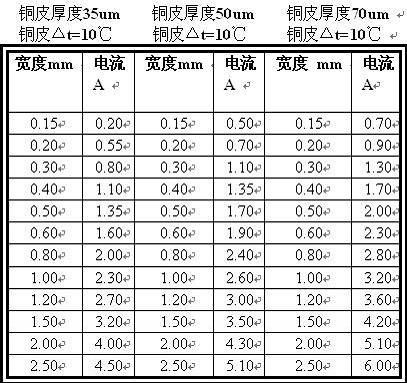
2. The current capacity of copper foil with different thickness and different width is shown in the following table:

Note: When copper foil is used as a conductor to pass large current, the current carrying capacity of the copper foil width should be considered by referring to the numerical derating of 50% in the table.
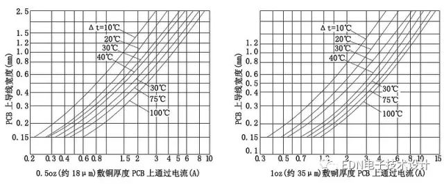
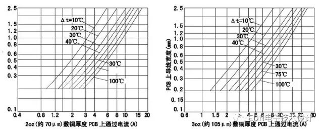
3. The relationship between copper foil thickness, trace width and current in PCB design needs to know what is called the temperature rise: after the conductor flows through, the current thermal effect occurs. As time passes, the temperature of the conductor surface continuously rises until it stabilizes. The stable condition is that the temperature difference between the front and rear within 3 hours does not exceed 2°C. At this time, the temperature of the conductor surface is measured as the final temperature of the conductor. The unit of temperature is degrees (°C). The portion of the rising temperature that exceeds the temperature of the surrounding air (ambient temperature) is called the temperature rise, and the unit of temperature rise is Kelvin (K). Some articles on temperature rise, test reports, and test questions often include the unit of temperature rise (°C), and unit cost (°C) indicates that the temperature rise is inappropriate.


Commonly used PCB substrates are FR-4 materials, copper foil adhesion strength and high operating temperature, the general PCB allowable temperature of 260 °C, but the actual use of the PCB temperature can not exceed 150 °C, because if more than this temperature It is very close to the solder melting point (183 °C). At the same time, the allowable temperature of the components on the board should also be taken into account. Normally, the civilian grade IC can only withstand a maximum temperature of 70°C, the industrial grade IC is 85°C, and the military-grade IC can only withstand 125°C. Therefore, the temperature of the copper foil near the IC on the PCB with the IC is required to be controlled at a relatively low level. Only higher-temperature devices (125°C to 175°C) can be used to allow higher copper foil temperatures. PCB temperature, but the impact of heat dissipation on the power device when the PCB temperature is high is also a consideration.
We are a professional manufacturer in the cabling solutions supplies in Ningbo, we could offer the Patch Panel in 8-48 ports, cat5e, cat6 cat6a specification; Metal or plastic Cable Management with brush; the Keystone Jack in UTP and STP style; surface wall mount box in blank, cat5e cat6 or other mount box; the RJ45 Modular Plug in 8P8C, cat5e, cat6, cat7 basing on UTP and STP Style; 86 type, UK type, France, type, German type, USA type Face Plate in 1 port to 8 ports; Stripper and Crimping tool and tool kits, cable tester for RJ11 RJ12 RJ45, HDMI,USB connector; cabling solution accessories like as cable tie, Cabinet screw, LSA module frame, indoor and outdoor distribution box, fiber optical distribution box and patch panel.
We have more 6 staffs in QC team, and 4 staffs in technical division to keep the high quality of products and service to our customers.
CAT5E Patch Panel,STP Patch Panel,24 Ports Patch Panel,keystone patch panel
NINGBO UONICORE ELECTRONICS CO., LTD , https://www.uniconmelectronics.com