Usually, the millimeter wave frequency band refers to a frequency of 30 to 300 GHz, a corresponding wavelength of 1 to 10 mm, a low-end adjacent centimeter wave band, a centimeter-band all-weather characteristic, and a high-end adjacent infrared wave band, and has an infrared band high resolution characteristic. For a long period of time, millimeter waves are mainly used in the military field. With the development of technology, the difficulty and cost of millimeter-wave applications have been greatly reduced. More and more industries and applications such as 5G communications and automobile anti-collision radars have started. Use millimeter wave frequencies.
The spectrum analyzer is one of the key equipments for millimeter wave testing. SerieCeyear4051L is the latest high-performance signal/spectrum analyzer with the widest range of coaxial coverage frequency in mainland China. It covers 3Hz to 67GHz coaxially. External frequency expansion up to 325 GHz.
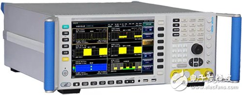
Figure 1,4051 series signal/spectrum analyzer
A · 4051L stand-alone easy to achieve 67GHz signal analysisThe 4051L is the only high-performance signal/spectrum analyzer with a coaxial coverage of 67GHz. The 67GHz display has an average noise level of -135dBm/Hz (typical) and is the industry's best receiver sensitivity.
Coaxial measurement has high measurement sensitivity with respect to external frequency extension, high measurement speed, pure spectrum, and high measurement accuracy. The number of cables used for coaxial connection is small, the test uncertainty due to mismatch and cable loss is reduced, the accuracy of millimeter wave band testing is improved, misdetection is reduced, the product quality is improved, and the smooth progress and cost reduction of R&D and testing are ensured. .
2 1 rich test function to help you measure millimeter wave signalsThe 4051 series of signal/spectrum analyzers provide spectrum analysis, power measurement components, IQ analysis, phase noise testing, transient analysis, pulse signal analysis and other test function selections within the frequency coverage; have good scalability and can be flexible. Configuration options further enhance test performance, and can also be used to build test systems or perform secondary development through various digital and analog signal output interfaces.
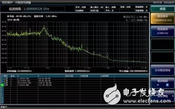
Figure 2-1, phase noise test
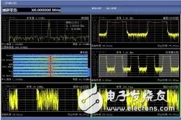
Figure 2-2. Transient Analysis
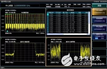
Figure 2-3 Pulse Signal Analysis
Third, external frequency expansion can achieve 325GHz millimeter wave signal measurementIs 67GHz not enough for you to use? There is also an external frequency extension function. Features of 4051 external spread spectrum include:
50GHz to 75GHz, 75GHz to 110GHz, 110GHz to 170GHz, 170GHz to 220GHz, 220GHz to 325GHz serialized band coverage.
The USB interface between the analyzer host and the spread spectrum module is used for plug and play. The spread spectrum module automatically identifies and automatically configures the conversion loss. No manual configuration is required.
The analyzer host software provides signal recognition capabilities with a strong ability to suppress false spectra.
The use of external spread spectrum function:
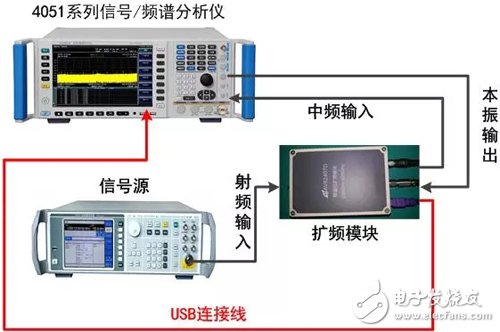
Figure 3, 4051 series signal / spectrum analyzer spread spectrum connection diagram
a) Connect the instrument as shown in Figure 3 (do not connect the red part temporarily). The output of the signal source is connected to the RF input of the spread spectrum module. The intermediate frequency output of the spread spectrum module is connected to the IF input of the spectrum analyzer. The local oscillator output of 4051 is connected to the local oscillator input of the spread spectrum module.
b) In spectrum analysis mode, connect the AV4051 to the spread spectrum module as shown in the red connection in Figure 3. At this point AV4051 automatically finds the spread spectrum module, as shown in Figure 3. The 4051 realizes the intelligent identification of the spectrum information of the spread spectrum module, automatically reads the conversion loss information configured in the module, and automatically switches to the corresponding spread spectrum frequency band. Because the harmonic mixer's IF output contains many mixing products, and there is no signal preselector in the spreading function path, many signals can be seen on the instrument screen, but only one of them is correct, as shown in the figure. 4 shows.
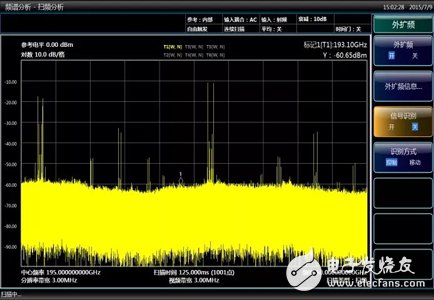
Figure 4, spread spectrum measurement results
c) Open the signal recognition switch in [Input/Output] and [Outside Spread Spectrum] menus. You can see that most false responses are suppressed, as shown in Figure 5.
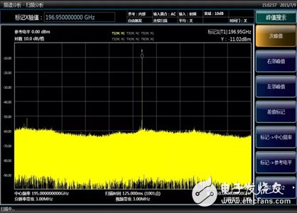
Figure 5. Spread spectrum measurement results when signal recognition is on
d) After the external spread spectrum test is completed, simply pull out the USB connection cable of the spread spectrum module, and the instrument will automatically exit the spread spectrum mode and restore to the coaxial measurement mode, which is simple and quick.
YLTelecom produces a variety of network faceplate, these faceplates are compatible with our keystone jacks. We have 86 type faceplate, 120 type faceplate, USA Type faceplate,UKtype faceplate, Australian Type Faceplate, French Type Faceplate, and also German Type Faceplate. These faceplate are available with 1 port, 2 port, 3 port, 4 port, 5 port, and 6 port. They are complaint with international standards and with good material. Due to high quality, our faceplate has recognized by international customers for many years.
We are Quality UTP / FTP Network Keystone Jack Plastic Faceplates with Shutter RJ45 Module manufacturers & exporter,we pffer you many type of Faceplate,like Rj45 Faceplate,Telephone Faceplates,86type Face plate.We can promise you the good quality and low price.

Network Faceplate, USB Faceplate, Rj45 Faceplate, Telephone Faceplates
NINGBO YULIANG TELECOM MUNICATIONS EQUIPMENT CO.,LTD. , https://www.yltelecom.com