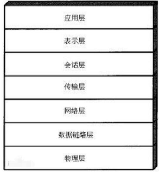
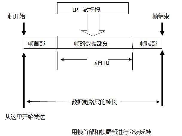
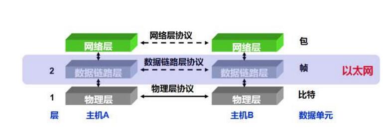
The data link layer is the second layer in the OSI reference model, between the physical layer and the network layer. The data link layer provides services to the network layer based on the services provided by the physical layer. The most basic service is to reliably transmit data originating from the network layer to the target network layer of the adjacent node. To achieve this goal, the data link must have a series of corresponding functions, mainly: how to combine data into data blocks, which are called frames in the data link layer, and frames are data links. The transport unit of the layer; how to control the transmission of the frame on the physical channel, including how to handle the transmission error, how to adjust the transmission rate to match the receiver, and the establishment and maintenance of the data link path between the two network entities And release management.

The LLC sublayer of the data link layer is used for error control, flow control of a single connection between devices. Unlike the MAC layer, LLC has nothing to do with physical media. It doesn't matter if the medium is CSMA/CD 802.3 or 802.5 Token Ring. It is independent of 802.2 in the LAN. The network layer above the LLC can be connectionless, responsive, connectionless or connection oriented different services.
LLC accesses the upper layer protocol with the service access point SAP. With SAP, the site can play with several high-level protocols simultaneously using only one interface in the LLC layer. An SAP is a simple address or protocol ID, and the content is an empty LLC frame. A LLC Protocol Data Unit (LLCPDU) is an LPDU. It includes: DSAP (destination SAP) / SSAP (source SAP); a control field (Controlfield) that defines throughput priority; and an information field with data. On the receiving side, the DSAP, for example the protocol ID, is the message to be delivered. Usually the DSAP and the SSAP are the same, because the two ends can only communicate between the same protocols. For example, when SAP is AA, it stands for SNAP (Sublayer Access Protocol). SNAP is a non-standardized, vendor-specific protocol used to access protocol services. For example, when SAP is 06, it represents IP protocol; when SAP is FO, it represents NetBIOS (Network Basic Input/Output Protocol). SAP stands for FF to broadcast the Global protocol.
SNAP mechanism
The canonical DSAP has only one byte, which is not enough to distinguish all protocols. SNAP is here, and it supports the vendor's protocol in the LLC frame upload. The protocol thus passed is placed in a so-called SNAP frame. The first three bytes of SNAP" phenolic paper are the manufacturer number, and the last two bytes indicate the protocol.
There are two versions of Ethernet: IEEE (802.2, 802.3); DIX (DEC, Intel, Xerox) is also known as V2 Ethernet. The DIX frame is followed by a two-byte Type, such as IP, after the source address.
The IEEE Ethernet frame, after the source address, is the frame length indication, which is the standard LPDU encapsulation in the subsequent data domain, including DSAP/SSAP/Control Domain/Data. There will be a protocol ID, an Ethernet type indication in this Data, for example, the Ethernet type 806 represents the Address Resolution Protocol ARP. The Ethernet card can be set to the required Ethernet version via a jumper or software. DIX is usually set up, as it is used by approximately 90% of the network. Please note that all sites on the network that need to communicate should be set to the same version.
2, the media access layerMedia access control is to solve the problem of how to allocate the right to use the channel when the use of the shared channel in the local area network competes.
Logical Link LogicalLinks
LogicalLinks A logical link is a protocol-driven communication session between two end systems that exchange communication information on actual circuits or logic circuits. The protocol stack defines the communication of two systems on a medium. A variety of different types of communication protocols are available at the lower level of the protocol stack, such as local area network (LAN), metropolitan area network (MAN), and icon X. 25 or a packet switched network such as Frame Relay. A logical link is formed between two communication systems on a physical link, which can be copper wire, fiber optics, or other medium. According to the OSI protocol model, these logical links exist only above the physical layer. You can think of a logical link as a line that exists between two networked systems in the network.
Connection-oriented services To establish reliable communication, logical lines need to be established, but sessions must be maintained between the two end systems. A logical line that is transmitted to a service packet that requires an answer connection and that has a return signal. This service creates more overhead but is more reliable. No answer No connection service does not require answering and pre-delivery. There is no session between the end systems.
The data link layer in the OSI protocol stack can be further subdivided into a lower Medium Access Control (MAC) sublayer and a higher Logical Link Control (LLC) sublayer. When it receives a packet, it passes up from the MAC sublayer. If multiple networks and devices are connected, the LLC layer may send packets to another network. For example, on a NetWare server, you might have both an Ethernet adapter and a Token Network Adapter installed. NetWare automatically bridges between the networks connected to the adapter so that packets originally on the Ethernet can be sent to the token network. The destination, the LLC layer is like the exchange between network segments or link relay, it reassembles the Ethernet frame into the frame of the Token Ring.
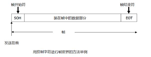
How the data link layer works 1. Framing (frame synchronization)In order to provide services to the network layer, the data link layer must use the services provided by the physical layer. The physical layer is transmitted in a bit stream. This bit stream does not guarantee that there is no error in the data transmission process. The number of received bits may be less than, equal to or more than the number of transmitted bits. Moreover, they may have different values. In this case, the data link layer uses a "frame" data block for data transmission to enable effective error control of the data. In order to transmit in frame format, there must be a corresponding frame synchronization technique, which is the "framing" (also called "frame synchronization") function of the data link layer.
The advantage of using the frame transmission method is that when a data transmission error is found, it is only necessary to retransmit the errored frame without retransmitting the bit stream of all the data, which is greatly improved in transmission efficiency. The advantage of using frame transmission is that it brings two problems:
(1) How to identify the beginning and end of a frame;
(2) In the data frame with intensive transmission, is the receiver recognized as a new data frame when receiving the retransmitted data frame, or is it recognized as a retransmission frame? This is identified by the various "frame synchronization" techniques of the data link layer. The "frame synchronization" technique allows the receiver to accurately distinguish the beginning and end of each frame from a bit stream that is not fully ordered, while also identifying retransmission frames.


In the process of data communication, some transmission errors may occur due to factors such as physical link performance and network communication environment. However, in order to ensure the accuracy of data communication, the probability of occurrence of these errors must be as low as possible. This function is also implemented at the data link layer, which is its "error control" function. In digital or data communication systems, error control is typically performed using anti-interference coding. Generally divided into four categories: Forward Error Correction (FEC), Feedback Detection (ARQ), Mixed Error Correction (HEC), and Information Feedback (IRQ).
The FEC method is to add enough redundant bits in a specific structure in the information code sequence - called "supervisor element" (or "check element"). The receiver decoder can automatically identify a small number of errors and correct them according to the specific supervision rules agreed by both parties. FEC is best suited for real-time high-speed data transmission.
In non-real-time data transmission, ARQ error control is commonly used. The decoder detects the error of the received code group one by one according to the coding rule. If there is no error, the acknowledgment ACK message is sent back to the sender; if there is an error, the ANK message is fed back to indicate that the request sender repeatedly sends the message that has just been sent. The advantage of the ARQ method is that there are fewer coding redundancy bits, and it has strong error detection capability, and the codec is simple. Since the error detection has little relationship with the channel characteristics, it has universal application value in non-real-time communication.
The HEC method is an organic combination of the above two methods, that is, automatic error correction is implemented within the error correction capability; and when the number of error bits of the error correction capability is exceeded, the error code can be found by detection, and the error code can be utilized regardless of the error code. The ARQ method performs error correction.
The IRQ method is a full-return type of simplest error control. In the error detection mode, the receiving end forwards the received signal to the transmitting end as it is, and compares it with the original transmitted signal. If an error is found, the transmitting end performs retransmission. Only suitable for low-speed non-real-time data communication is a relatively primitive approach.
3. Flow controlIn the data communication between the two parties, how to control the traffic of data communication is also very important. It not only ensures the orderly data communication, but also avoids the data loss caused by the receiver not being able to receive during the communication. This is the "flow control" function of the data link layer.
The transmission and reception of data must follow certain transmission rate rules, so that the receiver can receive the data sent by the sender in time. And when the receiver has no time to receive, it is necessary to control the transmission rate of the sender data in time so that the rates of the two aspects basically match.
4. Link controlThe "link management" function of the data link layer includes three main aspects of the establishment, maintenance and release of data links.
When two nodes in the network are to communicate, the sender of the data must know if the receiver is in a state ready to receive. To this end, both parties must first exchange some necessary information to establish a basic data link. The data link is maintained while the data is being transmitted, and the data link is released when the communication is completed.
5.MAC addressingThis is the main function of the MAC sublayer in the data link layer. The "addressing" mentioned here is completely different from the "IP address addressing" that will be introduced in the next chapter, because the address sought here is the MAC address of the computer network card, also called "physical address", "hardware address". ", not an IP address.
In Ethernet, media access control (MAC) addresses are used for addressing, and MAC addresses are burned into each Ethernet network card. This is necessary in the case of multipoint connections, because in such multipoint connection network communication, it must be ensured that each frame can be accurately sent to the correct address, and the receiver should also know which station the sender is.
6. Differentiate data and control informationSince the data and control information are transmitted in the same channel, in many cases, the data and control information are in the same frame, so there must be corresponding measures to enable the receiver to distinguish them so that the upward transmission is only true. Required data information.
7. Transparent transmissionThe term "transparent transmission" as used herein means that data of any combination of bits can be efficiently transmitted on the data link. This requires that when the bit combination in the transmitted data happens to be exactly the same as a certain control information, corresponding technical measures can be taken, so that the receiver does not mistake such data for some kind of control information. Only in this way can the transmission of the data link layer be transparent.

1, TCP / IP supports a variety of different data link layer protocols, depending on the hardware used by the network, such as Ethernet, Token Ring, FDDI and other local area networks, serial lines, X.25, Frame Relay FR, ATM Such as WAN.
2. In the early days, due to the competition of various network companies, the LAN did not form a unified standard. In order to integrate various LANs, the link layer was split into two layers, logical link layer (LLC) and media access control (MAC) ( 802.3 package: SAP),
In the 1990s and 1990s, Ethernet gained a monopoly position, and Ethernet became synonymous with LAN. The data link layer only needs the MAC layer and adopts the Ethernet frame format (EthernetV2 encapsulation: ARPA).
Installation Accessory,Encoder Sensor With Coupling,Encoder Sensor Wheel,Sensor Encoder
Yuheng Optics Co., Ltd.(Changchun) , https://www.yhencoder.com