1 grid voltage detection, high voltage detection and protection circuit
This article refers to the address: http://
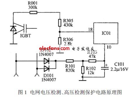
The principle of grid voltage detection and high voltage detection and protection circuit is shown in Figure 1.

The input voltage is proportional to the grid voltage. Based on this voltage, the microcontroller compares with the internal set value to determine whether the operating voltage is within its allowable range. If the allowable value range is exceeded, the IGBT tube drive output signal is turned off, that is, it is turned off, thereby acting as an overvoltage or undervoltage protection.
R001, R305, and R306 are connected in series and sampled at the c-pole of the IGBT tube, and the divided value is sent to the roll of the single-chip IC01. Based on this voltage, the MCU compares with the internal set value to determine whether the c-pole voltage of the IGBT tube is too high. If it is too high, the on-time of the IGBT tube is limited, the high level of the IGBT tube drive signal is narrowed, the on-time of the IGBT tube is shortened, and the c-electrode voltage of the IGBT tube is lowered, thereby providing overvoltage protection. The role.
2 voltage and current surge protection circuit
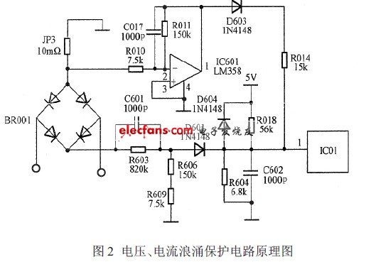
   The principle of voltage and current surge protection circuit of induction cooker is shown in Figure 2.

When there is surge pulse interference in the power grid, it is directly coupled by C601, and then divided by R606 and R609. After D601 is rectified, it is sent to pin 1 of IC01 of the single-chip microcomputer. The MCU turns off the IGBT tube drive signal, and the IGBT tube is cut off. Among them, C602 is a high-frequency bypass capacitor, D604 is a clamp diode, the main role is to prevent the surge sampling voltage sent to the microcontroller is too high and burn the microcontroller. When there is a current type surge pulse in the power grid, the constant copper pulse generates a high surge pulse (relative voltage to GND). This pulse is divided by R010 and R011 and sent to pin 2 of the operational amplifier IC601. Pin 3 is the reference voltage.
3 power-on delay protection circuit
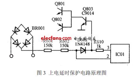
The principle of power-on delay protection circuit is shown in Figure 3.

The power-on protection circuit is mainly composed of R601, R602, D602, R810, Q803 and the like. When the power is plugged in, the +310 V voltage is stepped down by R601 and R602. After D602 is rectified, Q803 is turned on, so that the base voltage of Q801 is low level and the IGBT tube is turned off, thus protecting the IGBT tube.
4 current detection protection and detection pot circuit
When the current flows from the e-pole (GND) of the IGBT tube to the "-" end of the rectifier bridge through the constantan wire, a negative voltage is generated on the constantan wire with respect to GND, and the voltage is reversed by R012, C012, R016, and IC601. The phase amplifier is amplified, and then divided by R017, VR1, and R013, and then input into the roller of the single chip IC01 for processing. The voltage input to the single chip is proportional to the current flowing through the constantan wire.
Single Burner with Built in Hob
Single Burner Gas Stove,Stainless Steel Surface Hob,Single Burner Gas Cooktop,Single Burner Gas Hob
xunda science&technology group co.ltd , https://www.gasstove.be