Longlux Wall Pack Light delivers energy savings and reduced maintennce costs when replacing up to 400W HID fixture. Semi-cutoff light output is ideal for exterior walls, entrance ways and pathways.
  Heat and impact resistant borosilicate glass lens
  Die cast aluminum housing
  Options: Lens wireguard
          Visor option for full cut off
          Battery back-up
  Photocell compatible
  CCT: 4000K-5700K
  Lumen range: 4000-15000 lumens, up to 129LPW
  Five year limited OEM warranty
Specification
| Model | LLX-WL-40 | LLX-WL-60 | LLX-WL-80 | LLX-WL-100 | LLX-WL-120 |
| Power (W) | 40 | 60 | 80 | 100 | 120 |
| Voltage (V) | 110--277 | 110--277 | 110--277 | 110--277 | 110--277 |
| Hz | 50/60 | 50/60 | 50/60 | 50/60 | 50/60 |
| CCTÂ (K)Â | 4000-5700 | 4000-5700 | 4000-5700 | 4000-5700 | 4000-5700 |
| Luminous Flux @5000K, 120° (LM) | 4400 | 6600 | 8800 | 11000 | 13200 |
| CRI | 70 | 70 | 70 | 70 | 70 |
| Super bright chip | Lumileds | Lumileds | Lumileds | Lumileds | Lumileds |
| Driver | Universelite | Universelite | Universelite | Universelite | Universelite |
| Material | AL+Glass | AL+Glass | AL+Glass | AL+Glass | AL+Glass |
| Suitable Locations | wet | wet | wet | wet | wet |
| Beam angle | 100° | 100° | 100° | 100° | 100° |
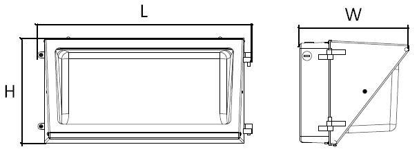
| Size(MM) | 360*259*190 | 360*259*190 | 360*259*190 | 463*232*235 | 463*232*235 |
| Life Time (H) | 50000 | 50000 | 50000 | 50000 | 50000 |
IMPORTANT SAFETY INFORMATION:
Input Voltage: AC 100-277V, 50/60Hz
Working Temperature: -25ºC~40ºC
This fitting must be wired in accordance with the National Electrical Code and applicable local codes and ordinances.
Installation and servicing this fitting should be performed by qualified electrician only.
Before installation or maintenance, turn off electric power and allow the fitting to be cool.
Proper grounding is required to insure personal safety. Carefully observe grounding procedure under installation section.
Ensure all electrical connections are secure & that there are no loose strands.
Install the fitting in a well-ventilated environment, keep away from corrosive/explosive materials, flammable gas or
electric dust.
Violent shaking or impact should be avoided when the fitting is working.
To weather proof your outdoor installation, be sure to seal all holes, conduit plugs with silicone caulking.
SUGGESTED METHOD OF INSTALLATION:
ALWAYS SWTICH OFF THE MAINS SUPPLY BEFORE INSTALLATION.
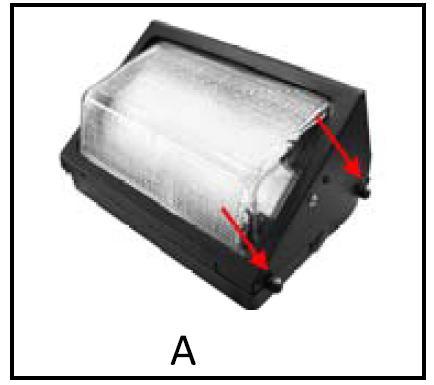
STEP 1: Open the Cover by unscrewing the Screws that are located on the side of the Wall Pack. (Fig. A).
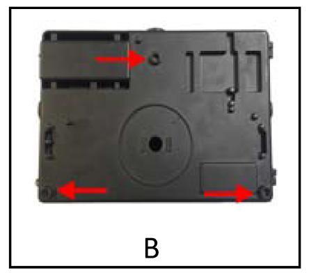
STEP 2: Drill Holes on Required Mounting Points (Fig. B) Â
NOTE: Holes Must not exceed 19/64" so that the structure of the Wall Pack is not compromised. Â
If holes exceed 19/64" or are made in any other part of the Wall Pack warranty will void.
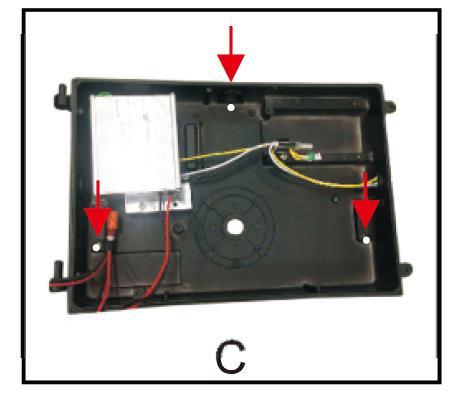
STEP 3: Mount Wall Pack by securing mounting screws (Not provided) on the drilled holes (Fig. C).
STEP 4: Do the wiring connections. (Refer to wiring instructions), and close the Cover by the Screws.
WIRING INSTRUCTION OF MAIN CABLE:

WARNING:
The product must be grounded and installed in accordance with the National Electrical Code and all local codes.
Failure to do so may increase the RISH OF PERSONAL INJURY, PROPERTY DAMAGE, FIRE AND DEATH.

 Feature
Longlux Wall Pack Light delivers energy savings and reduced maintennce costs when replacing up to 400W HID fixture. Semi-cutoff light output is ideal for exterior walls, entrance ways and pathways.
  Heat and impact resistant borosilicate glass lens
  Die cast aluminum housing
  Options: Lens wireguard
          Visor option for full cut off
          Battery back-up
  Photocell compatible
  CCT: 4000K-5700K
  Lumen range: 4000-15000 lumens, up to 129LPW
  Five year limited OEM warranty
Specification
| Model | LLX-WL-40 | LLX-WL-60 | LLX-WL-80 | LLX-WL-100 | LLX-WL-120 |
| Power (W) | 40 | 60 | 80 | 100 | 120 |
| Voltage (V) | 110--277 | 110--277 | 110--277 | 110--277 | 110--277 |
| Hz | 50/60 | 50/60 | 50/60 | 50/60 | 50/60 |
| CCTÂ (K)Â | 4000-5700 | 4000-5700 | 4000-5700 | 4000-5700 | 4000-5700 |
| Luminous Flux @5000K, 120° (LM) | 4400 | 6600 | 8800 | 11000 | 13200 |
| CRI | 70 | 70 | 70 | 70 | 70 |
| Super bright chip | Lumileds | Lumileds | Lumileds | Lumileds | Lumileds |
| Driver | Universelite | Universelite | Universelite | Universelite | Universelite |
| Material | AL+Glass | AL+Glass | AL+Glass | AL+Glass | AL+Glass |
| Suitable Locations | wet | wet | wet | wet | wet |
| Beam angle | 100° | 100° | 100° | 100° | 100° |
| Size(MM) | 360*259*190 | 360*259*190 | 360*259*190 | 463*232*235 | 463*232*235 |
| Life Time (H) | 50000 | 50000 | 50000 | 50000 | 50000 |

IMPORTANT SAFETY INFORMATION:
Input Voltage: AC 100-277V, 50/60Hz
Working Temperature: -25ºC~40ºC
This fitting must be wired in accordance with the National Electrical Code and applicable local codes and ordinances.
Installation and servicing this fitting should be performed by qualified electrician only.
Before installation or maintenance, turn off electric power and allow the fitting to be cool.
Proper grounding is required to insure personal safety. Carefully observe grounding procedure under installation section.
Ensure all electrical connections are secure & that there are no loose strands.
Install the fitting in a well-ventilated environment, keep away from corrosive/explosive materials, flammable gas or
electric dust.
Violent shaking or impact should be avoided when the fitting is working.
To weather proof your outdoor installation, be sure to seal all holes, conduit plugs with silicone caulking.
SUGGESTED METHOD OF INSTALLATION:
ALWAYS SWTICH OFF THE MAINS SUPPLY BEFORE INSTALLATION.
STEP 1: Open the Cover by unscrewing the Screws that are located on the side of the Wall Pack. (Fig. A).
STEP 2: Drill Holes on Required Mounting Points (Fig. B) Â
NOTE: Holes Must not exceed 19/64" so that the structure of the Wall Pack is not compromised. Â
If holes exceed 19/64" or are made in any other part of the Wall Pack warranty will void.
STEP 3: Mount Wall Pack by securing mounting screws (Not provided) on the drilled holes (Fig. C).
STEP 4: Do the wiring connections. (Refer to wiring instructions), and close the Cover by the Screws.


WIRING INSTRUCTION OF MAIN CABLE:

WARNING:
The product must be grounded and installed in accordance with the National Electrical Code and all local codes.
Failure to do so may increase the RISH OF PERSONAL INJURY, PROPERTY DAMAGE, FIRE AND DEATH.

Â
A circulator is a passive non-reciprocal three- or four-port device, in which a microwave or radio frequency signal entering any port is transmitted to the next port in rotation (only).
Applications
Isolator
When one port of a three-port circulator is terminated in a matched load, it can be used as an isolator, since a signal can travel in only one direction between the remaining ports.[12] An isolator is used to shield equipment on its input side from the effects of conditions on its output side; for example, to prevent a microwave source being detuned by a mismatched load.
Duplexer
In radar, circulators are used as a type of duplexer, to route signals from the transmitter to the antenna and from the antenna to the receiver, without allowing signals to pass directly from transmitter to receiver. The alternative type of duplexer is a transmit-receive switch (TR switch) that alternates between connecting the antenna to the transmitter and to the receiver. The use of chirped pulses and a high dynamic range may lead to temporal overlap of the sent and received pulses, however, requiring a circulator for this function.
In the future-generation cellular communication, people talk about full-duplex radios, where signals can be simultaneously transmitted and received at the same frequency. Given the currently limited, crowded spectrum resource, full-duplexing can directly benefit the wireless communication by twice of the data throughput speed. Currently, the wireless communication is still performed with "half-duplex", where either the signals are transmitted or received at different time frames, if at the same frequency (typically in radar), or the signals are simultaneously transmitted and received at different frequencies (realized by a set of filters called a diplexer).
Reflection amplifier
A reflection amplifier is a type of microwave amplifier circuit utilizing negative differential resistance diodes such as tunnel diodes and Gunn diodes. Negative differential resistance diodes can amplify signals, and often perform better at microwave frequencies than two-port devices. However, since the diode is a one-port (two terminal) device, a nonreciprocal component is needed to separate the outgoing amplified signal from the incoming input signal. By using a 3-port circulator with the signal input connected to one port, the biased diode connected to a second, and the output load connected to the third, the output and input can be uncoupled.
Rf Circulator,Passive Device Circulator,High Isolation Circulator,High Power Circulator,Waveguide Circulator,Optical Circulator
CHENGDU JING XIN MICROWAVE TECHNOLOGY CO., LTD , http://www.cdjx-microwave.com