LED lamps have been used in outdoor landscape lighting for more than ten years. Because of the convenience of LED control, the overall scale of such projects has become larger and larger, and the entire project has been tens of millions of yuan or even hundreds of millions of yuan. In this case, some technical blind spots that were not noticed began to appear.
Among these blind spots, the effects of power factor and neutral current are one of them. Although this problem is simple, but because of the lack of attention, the engineering problems, hidden dangers and waste are not small.
In the neon era, the ballast itself has a relatively high power factor, which causes fewer problems. In the LED era, the low-voltage switching power supply used usually does not have the PFC [L2] function, which has the following consequences:
1 In large-scale projects, because the power factor is too low, the power grid may be seriously polluted, and a large number of higher harmonics may cause interference to other equipment.
2 At the same time, the power factor is too low, which will increase the power load of the pre-stage equipment and increase user investment.
3 Causes the zero line current to be too large. In older circuits, due to the higher power factor and lower neutral current, the commonly used four-core cable is also based on this situation, and the neutral line diameter is smaller than the phase line.
4 Seriously excessive starting surge current will strongly impact the power grid, which is also a common problem.
Regarding the ordinary switching power supply, because the input rectification and filtering capacitor is large, the impact on the power grid is large at startup, which causes difficulty in closing. This point has been considered by the engineering design unit and some measures have been taken. This is not the focus of this paper. Switching power supplies with PFC function, because the input capacitance is much smaller, help to reduce the starting surge current.
This paper mainly describes and analyzes various situations of zero line current in high-power LED engineering using three-phase four-wire system.
1. Three-phase four-wire system phase separation uses a common switching power supply without PFC function. The total neutral current is approximately equal to the sum of the currents of the phase lines.
The usual misunderstanding is: 1 The current in the neutral line is the sum of the phasors of the three-phase phase currents, the three phase currents are equal in frequency, and the phase angles are 120o each other. If the three currents are equal in magnitude, the three currents cancel each other out. The phasor and just zero, there is no current in the zero line. The 2 zero line is used to pass the unbalanced current.
In fact, these statements only apply to switching power supplies with PFC function.
For switching power supplies without PFC function, the AC input is rectified and filtered with a large capacitor. In this case, the input current is in the form of a pulse. A typical input current waveform for such a switching power supply is shown in Figure 1.
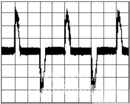
figure 1
In such a typical current waveform, the same current waveform of two phase shifts of 120° and 240° is superimposed, and the waveform of Fig. 2 can be obtained, so that three-phase balance is obtained, and three zero wires are connected to the three phases together. The total neutral current formed when the four-wire zero line.
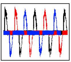
figure 2
It can be clearly seen that since all forward currents and negative currents do not occur simultaneously, the total neutral current is a simple superposition of three phase currents.
This type of waveform is of course not the only case that may occur when "three-phase four-wire split phase uses a normal switching power supply without PFC function". In this diagram, it is conditional that the forward current and the negative current do not appear simultaneously. If the filter capacitor after the rectification of the switching power supply is too small, or the load is heavy, the forward current and the negative current of different phases may overlap and cancel each other, then the total neutral current is no longer three phase currents. Simple overlays will be smaller.
For this reason, there are the following inferences:
Second, the three-phase four-wire system uses a switching power supply, and the total zero line must not be suspended.
The cost of the total zero line hangs, according to our engineering experience, it can be said that the engineering community is paying every day. The reason why the "without PFC function" is removed is because even if there is a PFC function, unless the three-phase load is particularly balanced, the total neutral current will not be zero, so it is not allowed to be disconnected.
For normal three-phase AC, the voltage between the phase and neutral lines is 220V, and the phase angle between the phases is 120 degrees. If the single-phase zero-line is open, of course, there is no problem. This phase has no electricity. If the total zero line is open, the median point will drift, the phase angle between the phases will change, and the magnitude of the change will be three. The load connected to the phase is related. At this time, the voltage on each phase is the vector sum of the adjacent two-phase voltages, causing the phase voltage of the load to increase and the phase voltage of the heavy load to decrease.
Figure 3 shows the case where the total neutral line is not connected and the phase voltage is abnormal. When using the power supply without PFC function, when the total neutral line is not connected, adjust the power consumption of the three phases separately, and actually measure the phase voltage. The blue voltage value obviously exceeds the power input voltage range. This happens in engineering, and the switching power supply may provide protection to a certain extent, but it usually causes power supply damage.

image 3
The emphasis on the zero line is one of the core issues of using three-phase four-wire AC power, and the importance of the neutral line and the corresponding engineering process must be very clear.
1 Use a switching power supply without PFC. Although the current on the zero line is usually close to or equal to the sum of the three phase currents, it usually does not produce more voltage drop than the phase line for each phase. This composite current is basically time-sharing;
2 copper and aluminum must be connected with copper and aluminum over-clamp or wiring nose;
3 The neutral wire busbar must be connected with the wiring nose, and the wiring nose must be properly crimped with hydraulic clamps;
4 Establish a zero-line operation and regularly check the files;
5 Periodically remove the oxidation and reinforcement of the neutral joint, and if necessary, apply conductive adhesive;
6 Prevent the total neutral line from floating due to wiring errors. Sometimes in order to deal with other problems, the phase line skips the sub-control circuit breaker. At this time, the neutral line must not be forgotten. Otherwise, the zero line will be suspended when the circuit breaker is not closed.
Third, three-phase four-wire system phase separation uses a switching power supply with PFC function, the total neutral current is determined by the power factor of each phase and the difference of each phase current.
Assuming that the power factor on each phase is ideal, a spreadsheet can be used to calculate the total neutral current. A style of the form is shown in Figure 4:
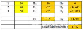
Figure 4
among them:
I1, I2, and I3 are three-phase currents, respectively.
I1x= I1*COS(0*PI()/180)
I2x=I2*COS(240*PI()/180)
I3x=I3*COS(120*PI()/180)
I1y=I1*SIN(0*PI()/180)
I2y=I2*SIN(240*PI()/180)
I3y=I3*SIN(120*PI()/180)
Inx=I1x+I2x+I3x
Iny= I1y+I2y+I3y
Total neutral current RMS: In=SQRT(Inx*Inx+Iny*Iny)
In actual use, the electrical parameters on the right side of the equation can be replaced by the corresponding cell coordinates.
Figure 5 below is a calculation of some typical cases of simulation.
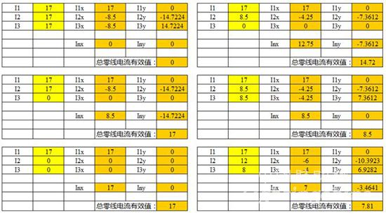
Figure 5
Comparing the calculated result with the actual measured result, it can be judged whether the switching power supply has a sufficiently high power factor. We use the following circuit for the verification test, and the result is very close to the theoretical calculation.
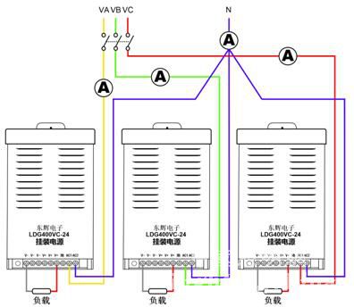
Figure 6
Fourth, the use of residual current protector RCD or leakage protector related to this problem.
In the case of power factor problems, especially in the absence of knowledge of the neutral current, some people will use a three-phase three-wire residual current protector in the system, and then find that it does not work and cannot be closed. This reason will not be repeated. The conclusion is that even if you use a switching power supply with PFC function, the protector will act as long as there is a three-phase imbalance.
Regarding the problem of the leakage protector, make an extension: Is it possible to use a three-phase four-wire leakage switch and connect the neutral line with no problem?
The actual situation is often not good, because the switching power supply in the project is required to input the grounding wire, and the switching power supply is usually connected to one or several high withstand voltages due to EMC and safety considerations. Small capacity capacitor. If you use a more sensitive leak protector, the instantaneous current charged by these capacitors will trigger the leakage protector action.
In addition to the impact of power-on, also because of these capacitors, the ground leakage current in the use of switching power supply is much larger than that of the power frequency transformer. In large projects, the number of switching power supplies is usually larger. These leakage currents are superimposed and will reach a large value, and the power supply is not grounded but not so large. In this case, the total leakage current value should be calculated and a leakage protector with a larger operating current should be selected.
V. Conclusion:
Based on theoretical explanation and engineering practice, this paper points out the necessity of using PFC function switching power supply in large-scale LED outdoor engineering, and summarizes the zero-line related problems that have not been fully paid attention since the LED was applied to outdoor engineering. The author hopes to provide reference for industry practitioners and make a contribution to the standardization process of LED outdoor engineering.
references:
GB13955-2005 "Residual current action protection device installation and operation"
(This article has been reviewed by the reviewer, and the chief engineer of the International Building Design Consultant Co., Ltd. (CCDI Group) and the professor-level senior engineer Li Binghua reviewed the manuscript)
Editor: Yingzi
Silicone USB Cable,Micro USB Type,Micro USB Cable,Lightning Data Cable
Dong guan Sum Wai Electronic Co,. Ltd. , https://www.sw-cables.com