Past radar (RADAR) systems are mostly used in aviation equipment, but the industry has also found that radar has great potential for development in automotive applications, so they have invested in design. In particular, the solution implemented at the 77GHz frequency in the millimeter wave band is the most popular, because this band can absorb water molecules to the maximum, and it has been proven by the industry to be suitable for the development of automotive radar components and short-range radar (relative to aerospace).
Although most short-range radars still operate in the 24GHz band, in the long run, this band cannot guarantee global universality, and 77GHz radar will have some room to play. At present, 77GHz radar sensing technology has a place in advanced driver assistance systems (ADAS). In order to continuously improve the quality of the ADAS system and optimize the design cost, application designers must understand the design methods of 77GHz radio frequency (RF) technology required for transmitting and receiving radar waves, radar sensors with fundamental frequency signal processing functions, and radar system functional safety. .
Raising the cost performance of radar RF components: silicon germanium carbon BiCMOS process rise
Millimeter-wave radar systems rely heavily on III-V semiconductor components. Most automotive radar systems now use gallium arsenide (GaAs) technology to implement RF front-end circuits; however, silicon-germanium-carbon (SiGe: C) technology used to manufacture mobile phone components also It can create RF functions comparable to gallium arsenide at a very low cost, allowing consumers to install automotive ADAS at a reasonable price. In addition, through the fast, high-performance complementary metal oxide semiconductor (CMOS) process, the device performance can greatly exceed the chip solutions produced in the 90-nanometer (nm) process.
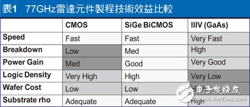
Table 1 analyzes the performance advantages of various radar component process technologies. Although GaAs has good substrate isolation benefits, each chip can achieve a higher circuit density, however, the achievable logic density (for control circuits) is very low; moreover, compared with the high efficiency achieved by mainstream chip technology , GaAs wafer materials are still relatively expensive.

In fact, compared with ordinary silicon wafers, III-V materials are more difficult to process. The size of III-V wafers or substrates is usually less than half of silicon wafers. As for the cost of gallium arsenide wafers entering the processing facility, it will be ten times higher. Twenty times, but after manufacturing, packaging and testing the cost difference will narrow.
At the same time, the CMOS process that belongs to the advanced technology node can provide very good logic density and cost, but its low breakdown voltage designed for high-performance computing is difficult to meet the requirements of the automotive industry. It is reliable and must support medium and long-distance operation. The required power level.
As for the silicon-germanium-carbon technology option, there are no serious shortcomings for the radar component. After using the traditional BiCMOS process enhanced by the millimeter-wave process module, it can effectively overcome all the above problems. The process module provides a bipolar transistor (HBT) structure using silicon germanium-carbon materials to achieve higher electron mobility to convert to faster operating speeds.
The BiCMOS process provides sufficient efficiency to add cost-effective control structures to digital control interfaces such as phase-locked loops (PLL) and serial peripheral interfaces (SPI). Breakdown and power gain data supports the transmit circuit at power levels higher than 13dBm, while providing sufficient isolation to integrate multiple receiver channels on a single chip.
The design of radar system using FMCW mechanism is greatly simplified
In terms of automotive radar signal modulation, most schemes use frequency modulated continuous wave (FMCW) mechanism, which simplifies system complexity and improves efficiency. With a continuous carrier signal, its frequency will change according to a pre-defined schedule, such as a time ramp, etc. The range in which this frequency change occurs defines the bandwidth of the radar system. For an ordinary 77GHz radar, there is a 1GHz time slot allocated around 76.5GHz and a 4GHz time slot allocated around 79GHz. Generally, the 77GHz frequency range corresponds to long-range radar sensors; the 79GHz frequency range is related to short-range radar systems.
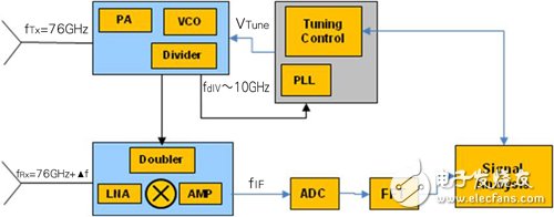
The radar transmitter is usually equipped with a local oscillator (LO) that can be continuously tuned by the PLL, which generates the frequency sweep rate. Figure 1 shows a highly integrated radar sensor architecture. On the transmitter chip, a voltage-controlled oscillator (VCO) generates a 77GHz frequency signal, which is amplified by a power amplifier (PA) and sent to the transmission antenna. The tuning voltage of the VCO is generated by the integrated PLL circuit in the transmitter chip. Therefore, a high frequency scan rate is very important to achieve a high target speed accuracy.

Figure 1 Radar sensor design architecture
Remote Control Panel,Magnum Remote Panel,Remote Screen Panel,Magnum Energy Inverter Control Panel
SUZHOU DEVELPOWER ENERGY EQUIPMENT CO.,LTD , https://www.fisoph-power.com