Abstract: In order to demonstrate the role of ESP in improving the stability of vehicle handling, combined with the technical knowledge of electronic professional, through the design of circuit diagrams and simulation of circuit diagrams, and the application of related electronic components, the ESP pre-war warning on the toy car is active. Control function, the physical operation is good. The design ideas and methods can be applied to more students.
Keywords: automotive active safety; ESP; simulation design; acceleration sensor
0 Introduction ESP (Electronic Stability Program) is an active intelligent security system that monitors the driving status of a car at all times through highly sensitive sensors, and identifies dangerous situations in time to stabilize the car. The ESP system was first developed by Bosch in Germany in 1997. The company's statistics show that the application of ESP in automobiles has reduced the traffic accident rate of passenger cars by 20% to 50%. In recent years, ESP's excellent performance in driving has been recognized more and more. The ESP assembly rate of new cars worldwide has been significantly improved. According to the statistics of Bosch in Germany, the ESP assembly rate of new cars in Germany was about 72% in 2005. The average assembly rate of new cars is about 44%, about 21% in North America, and about 15% in Japan. In 2006, the assembly rate of our domestic ESP was only 3%, far lower than that in Europe and America. Today, in 2012, the ESP equipment situation of domestic vehicles is still not optimistic, only 18%, only reaching the level of South Korea in 2006. Compared with foreign countries, the research on automobile dynamic stability control in the domestic automobile industry started late, and the assembly rate of domestic ESP is still relatively low. Due to the gap between science and technology, most scholars only study the ESP and stay on theoretical research and Simulation simulates the specific problems encountered in the design of ESP systems. Similarly, this part of the market is completely in the hands of foreign-funded enterprises, and domestic enterprises can hardly get involved. Therefore, efforts should be made to overcome the theory and key technologies of ESP design, which is important for improving the independent development capability of domestically produced vehicles and shortening the gap with developed countries. Realistic meaning.
This article is based on the principle of ESP electronic body stability system, combined with the technical knowledge of electronic professional, through the design of the circuit diagram and the simulation of the circuit diagram, theoretically achieve the purpose of ESP system to alert the driver and actively brake the car, and apply related electronics Components, simulate the ESP system's pre-warning and active control functions on the toy car. This design demonstrates the role of ESP in improving vehicle handling stability.
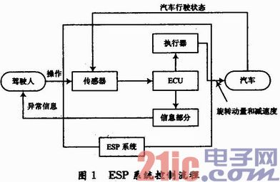
1 ESP Controls Automotive Motion Process The ESP Electronic Body Stability System is an active safety system that improves vehicle curve stability. When an abnormal situation occurs, the ESP will respond according to the actual situation, instead of blindly obeying the driver, so that the driving safety of the car is greatly improved. The ESP computer calculates the theoretical value of maintaining the stability of the vehicle body, compares it with the data measured by the yaw rate sensor and the lateral acceleration sensor, and issues a balance correction command to make the car return to the predetermined orbit, and maintain the control system of the normal driving system of the vehicle as shown in Fig. 1. Shown.
This article refers to the address: http://

The basic control program is as follows:
(1) Under normal driving conditions, the ESP control unit (ECU module in the figure) receives signals from the steering wheel angle sensor and the wheel speed sensor, and after calculation and monitoring, knows the direction information of the driver's stable driving of the vehicle, and Store this data.
(2) The ESP control unit ECU simultaneously receives signals from the yaw rate sensor and the lateral acceleration sensor, and calculates the state of the actual vehicle traveling. The data is compared with the data monitored in (1) to determine whether the vehicle is in a stable driving state at this time (the driver's direction information of the vehicle's steering and the direction of the stable driving are consistent with the vehicle's stable driving state).
(3) After comparison, if the two information are consistent, the ESP control unit determines that the car is in a stable state of safe driving at this time, and the ESP system is in a standby state. If the two information are inconsistent, the ESP control unit determines that the car is in an unsteady driving state at this time, and the ESP control unit issues a control command to the actuator (hydraulic adjustment unit), and through the interference of the engine, the hydraulic actuator is used to manufacture each wheel. To correct the unstable driving state of the vehicle in time to ensure personal safety.
2 ESP electronic body earing system simulation design
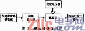
2.1 Simulation design ideas and principles According to the principle of ESP electronic body stability system, the biggest feature of ESP is its initiative, which can remind the driver in time when danger occurs, and play the role of prior warning. Figure 2 is a flow chart of the design of the circuit board of the early warning function module. The value of the acceleration sensor is compared with a preset voltage value (simulating the stability value of the electronic control unit of the actual ESP system), according to the actual model car driving situation. It is judged whether it is accelerated to the left or to the right, so that the driver is warned by the light of the indicator light, and the unstable running state of the vehicle appears.

2.2 Circuit schematic of the analog design During the actual driving process of the car, due to various reasons, such as side slip or over-steering, avoiding obstacles and other emergencies, the ESP electronic body stability system will actively sense the instability of the car. State, the electronic control unit actively takes interventions to prevent accidents by analyzing and judging the data collected by each sensor. However, in the actual test, due to the difference of experimental conditions, it is impossible to simulate the processing process of the real car in distress, mainly in the case of the simulated car in the case of rapid turning, the experimental car has unstable driving state, and the ESP electronic body is stable. The system begins to enter the working state from the standby state.
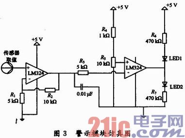
FIG. 3 is a process of simulating the process of collecting signals, and sequentially amplifying and comparing the collected sensor signals, thereby judging the running state of the experimental car by the LED light.

2.2.1 Voltage Amplification Module In the module of this design, the voltage signal collected by the acceleration sensor is weak due to the limitation of the speed of the experimental car itself, and the voltage signal needs to be amplified. The chip LM324 is mainly used to amplify the analog signal for later voltage comparator processing. Due to the special nature of the accelerometer chip used, the output analog voltage is about 1.2 V at 0 g or at rest. After the voltage amplification module, the voltage is amplified from the original 1.2 V to about 1.8 V. . It can be seen from Fig. 3 that the voltage output from the pin 1 is 1.8 V according to the voltage amplification of the same example. According to the schematic diagram of the design, the ratio of the two resistors on the feedback loop is known, and the operation magnification is 3 times. Since the LM324 op amp is powered by a 3 V DC power supply during the actual test, the analog amplifier is not amplified by 3 times in theory, but only amplified by 1.5 times, and the amplified 1.8 V analog voltage signal. After the filter circuit, it is connected to the 6 pins of the comparator and compared with the set voltage value.
2.2.2 Voltage Comparator Module In the voltage comparison module, the LM324 chip is selected as the comparator, and the comparator inputs the set voltage value in the forward direction to simulate the data of the car during steady driving, which is measured by the actual car. The experimental data is connected to the comparator negative input. Under ideal conditions, when the actual measured voltage value is less than the set voltage, the comparator logic is high. According to the circuit schematic, LED1 does not emit light, and LED2 emits light. On the contrary, if the actual measured voltage data is greater than the setting When the theoretical value is determined, the comparator logic is low, and the LED1 lamp emits light and the LED2 lamp does not emit light. Through the LED's on and off, it is judged whether the car is at a high acceleration or not.
During the test, since the supply voltage of the voltage comparator is also a 3 V DC power supply, once the module is powered up, the LED 1 will light up, indicating that the circuit is working properly, simulating the safe state of the actual vehicle driving, and the ESP does not work at this time; When the acceleration sensor senses a dangerous state and outputs a large voltage of the analog voltage, the experimental car does not travel in a predetermined state. At this time, the LED 2 is turned on, and the LED 1 is turned off, and the LED 2 is lit to issue a warning that the car is in an unstable driving state at the same time. It also indicates that the car's ESP system should enter the working state from standby. In the actual demonstration process, after several tests, it is appropriate to set the voltage value to 1.8 V.
2.3 Simulation design of the experimental brake module When the ESP electronic body stabilization system is working, when the ECU receives the signal from the wheel speed sensor, the electronic control unit will issue the relevant command to the actuator-hydraulic regulator. The hydraulic regulator actively adjusts the unstable state of the vehicle by controlling the braking circuit of each wheel, corrects the driving direction of the vehicle in time, and makes the vehicle actively return to the predetermined traveling track to ensure driving safety.
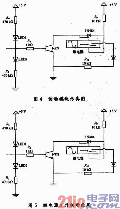
2.3.1 Principle analysis of the simulation design of the brake module Considering that the drive module of the experimental car already exists, the drive module cannot be interfered. In the analog design, the relay is used to temporarily brake the rear-wheel motor of the trolley. The relay mainly functions as a conversion circuit to control the relay operation through the conduction and cut-off of the triode NPN9013. When the relay is working, the relay coil has a current passing through it, generating electromagnetic force, attracting the internal armature conversion circuit of the relay, and cutting off the rear wheel motor. In the working circuit, the motor stops working; after a short time, the relay is de-energized, the internal switch actively returns to the original position, and the car continues to work.
2.3.2 Simulation principle of braking module simulation design This design module mainly simulates the active interference effect of the ESP electronic body stability system on the driving state of the car. As can be seen from FIG. 4, when the pre-warning warning module obtains a logic high level, the base of the triode is at a high level. At this time, the triode is turned on, and the relay coil instantaneously passes current, generating electromagnetic force, and attracting the armature. The internal switch of the relay in Fig. 4 is shifted from the static contact to the movable contact. At this time, the circuit is turned on, and the LED 4 is lit. , indicating that there is a signal input and the signal is high.

During the experiment, the voltage of the brake module of the experimental car cannot be dynamically tested. The rear wheel motor of the car can only be controlled by the conversion circuit function of the relay. The common end of the relay and the position of the static contact are connected to the rear wheel motor. The loop is used to determine if the car is being braked. In the simulation process of the circuit diagram, due to hardware reasons, the internal switch of the relay is not directly changed. Therefore, the LED4 lamp is connected to the circuit, the test circuit is working, and the LED4 lamp is lit, indicating that the circuit works normally, see Figure 5.
It can be seen from the simulation diagram that when the car has a sharp turn, the voltage comparator outputs a logic high level, and the LED2 lamp emits light, which in turn warns the driver of the unstable running state of the car, and the high level is about 3.8 V. The base voltage of the triode is about 0.89 V. At this time, the triode is turned on, and the voltage across the relay coil is about 4.9 V. Since the operating voltage of the relay is 5 V, the relay coil has a current passing through it, generating an electromagnetic force. The armature inside the relay is changed from the static contact to the moving contact. Since the common terminal is connected to the 6 V voltage, the circuit is turned on and the LED 4 is illuminated. At this time, the relay is completed. When the experimental car is running normally, the voltage comparator is low. At this time, the triode is turned off, no current flows through the coil of the relay, and the relay remains in the original state.
2.3.3 The physical map of the experimental car The actual object of the experimental car is shown in Figure 6.

3 Conclusion This paper introduces the working principle and control flow of the ESP electronic body stabilization system, combining theory with practice to simulate the ESP system's effectiveness in the driving process. By designing the circuit diagram and simulating the circuit diagram, the purpose of the ESP system to alert the driver and actively brake the car is theoretically achieved. In the analog design warning module, the analog signal collected by the acceleration sensor is amplified and compared to obtain high and low logic levels. When a logic low level occurs, the ESP system is in a standby state; when a logic high level occurs, correspondingly The LED light is on, indicating that the ESP system is in a working state from the standby state. At this time, the brake module receives the command and starts to interfere with the driving state of the trolley. The relay conversion circuit changes the internal armature from the static contact to the movable contact, and cuts off the driving circuit of the rear wheel motor of the trolley to achieve the braking purpose.
Due to the limitation of experimental conditions and the gap between theory and practice, the experimental vehicle captures the dangerous signal for a short time during the rapid turning, the LED light is instantly lit, the relay works to cut off the drive circuit, and the brake car, this When you control the movement of the car, you can only judge whether you want to go forward or backward by the signal indicator.
In a word, this paper uses the simpler design idea to realize the demonstration of the role of ESP system in improving the steering stability of the car during the driving process. The trajectory followability of the car model is better. It is hoped that this design idea will have a certain auxiliary effect on the theoretical teaching and practical teaching of the electronic major. It will enable students to comprehensively apply what they have learned in the process of exploration, and connect theory with practice to improve the ability to find problems and solve problems. The simulation design works well, and the design ideas and methods can be applied to more students.
We are a legal e-cigarette trader in China, We can provide you with IGET Disposable Vape, vape 600puffs/1200puffs/1800puffs/2300puffs/2600puffs/3000puffs/3500puffs/4000puffs/5000puffs.supplier the largest selection of disposable vape from China. and deliver to the destination just cost 7-15davs. Over 1000 products available now! High-quality
Sufficient supply and favorable price, If you need to pick up goods wholesale, don't miss us


IGET Vape,IGET Disposable Vape 1500Puffs,XXL IGET Disposable E Cigarette,Pen style disposable electronic cigarettes
TSVAPE Wholesale/OEM/ODM , https://www.tsvaping.com