Since digital technology entered the audio field, the sound quality of the sound source and input system has been greatly improved, and the preamp has become a simple thing that is almost just a sound source selection switch and a volume potentiometer. But on the contrary, the output system has not changed much as it was in the analog era, because the principle of the speaker has not changed much. Because the sound frequency range is as wide as nine to ten octave bands, it is very difficult to make the vibration system of the speaker to vibrate completely linearly according to the electrical signal in such a wide frequency range, and it is almost impossible to require linear sound radiation characteristics. It is almost impossible of.
A solution is to divide the audio frequency range into several segments. Then use several speakers to play in sections, which is a multi-speaker system, and the two-unit and three-unit systems are common. However, dividing the frequency band requires a frequency-dividing network. Generally, L and C filters are inserted between the power amplifier and the speaker. Because the speaker is not a pure resistance component, it brings difficulties to the design of the frequency divider, and it is not easy to obtain good performance; and high-quality frequency dividers need to use high-quality inductors and capacitors, which are expensive.
In addition, because the efficiency of various speakers is different (the tweeter is about 6 dB higher than the woofer), in order to balance the sound pressure of the entire frequency band, it is necessary to insert an attenuator in the crossover to reduce the level of the high-efficiency speaker. The result The entire speaker system becomes a combination of several least efficient speakers.
In order to change this situation, a multi-channel amplifier method was created.
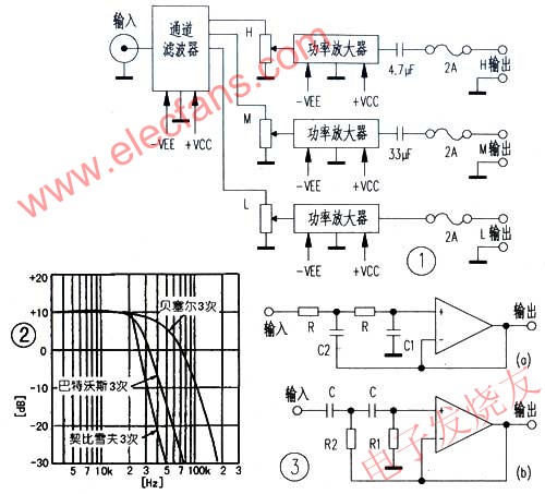
After the preamplifier, an active filter is used to divide the frequency band. Each frequency band has its own power amplifier and speaker. The level of each frequency band is adjusted by a potentiometer before each power amplifier. The advantages of this method are obvious, it eliminates the aforementioned LC network, and can effectively use the efficiency of each speaker; at the same time, it also reduces the frequency requirements of the power amplifier, and the output power can also be smaller; this structure is shown in Figure 1, the key circuit is an active filter.

Filters include low-pass, high-pass, band-pass filters, and band-stop filters. The low-pass filter allows components from zero frequency to its cut-off frequency to pass; and blocks components above the cut-off frequency; the high-pass filter blocks components below its cut-off frequency and allows components above it to pass: band-pass filter Frequency components between its low and high cut-off frequencies are allowed to pass, and all frequency components outside this frequency range are blocked.
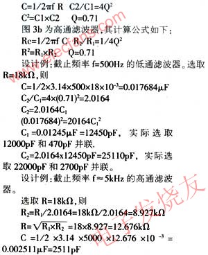
Active filters using op amps can eliminate inductive components and obtain voltage or current gain. According to the different cut-off characteristics of the filter, it can be divided into Bessel type, Chebyshev type and Butterworth type. The characteristic curve is shown in Figure 2, which is mainly shown near the cut-off frequency. The Bessel type declines slowly, and the Chebyshev type declines Steep, but the Butterworth type boundary lies between the two. The cut-off characteristic is usually expressed in decibels of the octave attenuation. The attenuation of the second-order filter is 12 decibels per octave, and the third-order filter is 18 decibels. Figure 3 is the standard Butterworth second-order Active filter. Figure 3a is a low-pass filter, and its calculation formula is as follows:

R1 actually chooses 18k Ω, R2 actually chooses 9.1k Ω, C actually chooses 2200pF and 270pF in parallel.
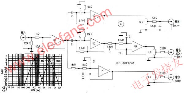
Figure 4 is a schematic diagram of a 12dB three-channel electronic crossover for audio. Selecting multi-channel pre-frequency division can obtain better sound quality than that after power amplifier. The frequency range of the three-channel crossover is low frequency ~ 500Hz:
Intermediate frequency 500Hz ~ 5kHz; high frequency 5kHZ. The frequency characteristics of their synthesis are shown in Figure 5.

Its low-frequency filter and high-frequency filter are the previous design examples: the intermediate frequency uses a band-pass filter. It is composed of a first-level high-pass filter and a first-level low-pass filter. The calculation and design of its R and C The example is the same. Setting the low-pass filter after the high-pass filter here can reduce the residual noise. Setting a buffer before the filter is helpful for matching with the sound source. The 1k Ω and 150pF at the input end are used to limit the input signal bandwidth: each filter The output end of the is adjusted with 10k 1kΩ wire wound potentiometer for output level adjustment.
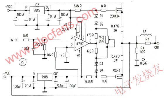
The output signals of the three-way filter are respectively connected to the same three power amplifiers, and the circuit is shown in FIG. 6. First use the input stage as the FET op amp LF357 as the current buffer, the final power amplifier tube uses high frequency characteristics of MOSFET, the bias circuit is composed of diode and resistor. Use the semi-variable resistor VR2 to set the quiescent current, the quiescent current can be measured Measure the voltage across the source resistance (0.47 Ω) when there is no signal. Then use the formula I = "U" / R to calculate. The final negative feedback is added from the source of the MOSFET to the inverting terminal of the op amp. Because the power supply voltage of the operational amplifier used for driving cannot be too high, the maximum output of the power amplifier is limited. If the power supply voltage of the op amp is ± 15V, the maximum output voltage of the driver stage is ± 12V = 24V, and the speaker impedance RL = "8" Ω, the maximum output power of the final stage P = "Vcc" × (VCC / 8RL) = 24 × 24 / 64 = 9W. This power seems to be too small, but in fact this is only the output power of one frequency band, plus the output power of the other two frequency bands, it has been fully applicable.

In Figure 6, Rx, Cx, LY, and RY at the output of the power amplifier are designed for stable circuit operation. Because the speaker is not a pure resistance component, when the frequency increases, its inductance component will become larger, which is equivalent to lighter high-frequency load and higher high-frequency gain, which may cause circuit oscillation; adding Rx equivalent to high-frequency load can avoid it oscillation.
When a long cable is used to connect the power amplifier and the speaker, due to the presence of the cable capacitance, it will increase the high-frequency load and make the power amplifier work unstable; adding LY and RY can avoid this situation. LY and RY are made of densely wound 10 turns of 1mm diameter enamelled copper wire on a 101 Ω 5W carbon film resistor.
In order to protect the speaker, a 2A fuse should be connected at the output of each amplifier, and a 2.5 μF polypropylene capacitor should be connected between the amplifier and the speaker in the high-frequency channel to protect the high-frequency speaker.
As long as the resistance and capacitance numbers of each channel filter are accurate, generally no debugging is required. Adjustment of the power amplifier: adjust VR1 when there is no signal input so that the output voltage is 0V, and then adjust VR2 so that the source resistance is 0.47 Ω and the voltage across the end is 0.1V (About 200mA).
HYAKKI Vape,HYAKKI Vape 2500Puff,Hyakki Fragrant Mango,HYAKKI Disposable Vape,HYAKKI Vape Kit,HYAKKI Vape Pod
TSVAPE Wholesale/OEM/ODM , https://www.tsecigarette.com