1 System Description
This article refers to the address: http://
A tire pressure monitoring sensor is installed inside each wheel, which can accurately measure the pressure and temperature inside the tire. The sensor sends the pressure value and temperature of the tire to the Body Control Model (BCM) according to a certain law through wireless. Value, BCM sends the information frame to the dashboard through the CAN bus, and the driver obtains the pressure value and temperature value of each tire through the dashboard display. When the pressure value or temperature value of a certain tire changes beyond the alarm value, the instrument panel can accurately display the position of the alarm tire and issue a graphic, sound, and text alarm. At the same time, the low-frequency antenna installed at each tire fender position communicates with the BCM, and the BCM needs the car tire pressure monitoring sensor to analyze and convert the operation information into 125 kHz low-frequency wireless data transmission, and the car tire pressure monitoring sensor This low frequency wireless signal will be received and then operated according to the parsed operational information. The above is the TPMS two-way communication system. Since this product is a safety product for automotive products, it should have high reliability in various environments. The various environments are: various weather conditions, such as cloudy weather, rain and other different weather conditions; various road conditions, such as national roads, High speed, country roads, mountain roads, etc.; snow roads, ice surfaces, extremely cold areas (-40 ° C) in winter; hot and humid areas in summer (surface temperature + 50 ° C, 90% humidity); different speeds ( 0 to 200 km/h). This requires strict selection of individual devices when designing automotive tire pressure monitoring sensors.
2 circuit design
Since the tire pressure monitoring sensor is installed inside the tire and is not in contact with the outside world, it requires that the maintenance cannot be performed too frequently. Generally, it requires a working life of 10 years, and its operating temperature range is -40 to +125 °C. It is required that the selected device be automotive grade and low power components.
The block diagram of the automobile tire pressure monitoring sensor system is shown in Figure 1.
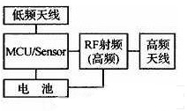
Figure 1 Block diagram of the car tire pressure monitoring sensor system
2.1 Sensor selection
The MCU/Sensor is the core of the system and is implemented by Infineon's SP300V2.1-E106-0. SP300V2.1-E106-0 integrates silicon micromachined pressure sensor, temperature sensor and accelerometer and a battery voltage monitor, and integrates a low-power 8-bit Harvard RISC controller; it has power-off Four modes of operation, running, idle, and shutdown, and three wake-up modes: IT/LT wake-up, PORT wake-up, and LF low-frequency detection wake-up, which can effectively meet the system low-power design requirements. The pressure measurement range is 0 to 3.5 Bar; the temperature measurement range is -40 to +125 °C; the centripetal acceleration measurement range is -12 g to 115 g; and the operating voltage range is 1.8 to 3.6 V.
2.2 RF unit selection
RF RF chips are mainly used to convert digital signals into high frequency signals. The system uses Maxim's MAX7044 chip, which operates from +2.1 to +6.0 V, 8 mA low operating current, 00K/ASK modulation, communication rate up to 100 kbps, small package 3 mm × 3 mm, 8 pins S0T23 package. It eliminates the problem of SAW-based transmitter design; it uses a crystal structure to provide greater modulation depth and fast frequency response; reduces temperature effects over a temperature range of -40 to +125 °C. The inside includes a power amplifier (PA), a crystal oscillator, a driver, a data activity detector, a lock detection circuit (10ck detect), a phase locked loop (32xPLL), and a frequency divider. (16 divide by frequency) and other circuits.
The MAX7044 has an automatic low-down mode control. If the DATA pin does not operate for a certain amount of time (wait time), the device automatically enters a low power mode. The wait time is approximately 216 clock cycles and is approximately 4.84 ms at 433 MHz. The wait time to enter low power mode is: Among them, fRF is the radio frequency transmission frequency. When the device is in low power mode, the crystal and PLL are "hot" on the rising edge of the DATA signal. The crystal and PLL require 220μs settling time before data is transmitted. The relationship between the reference frequency and the carrier frequency is: fXTAL=fRF/32.
The main characteristics of the MAX7044 are as follows:
◆+2.1~+3.6 V single power supply
â—†OOK/ASK transmission data format
â—†Maximum data rate 100 kbps
◆+13 dBm output power (50 Ω load)
â—† Low supply current (typical 7.7 mA)
◆250μs fast start time
The transmission circuit diagram composed of MAX7044 is shown in Figure 2. In actual design, according to the actual impedance of the antenna and the input impedance of the RF transmitting chip, the impedance matching between the RF transmitting chip and the antenna is completed by the π-type matching network to achieve the maximum power output.
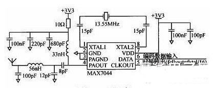
Figure 2 Transmitter circuit diagram composed of MAX7044
2.3 Battery selection
The battery selects the high temperature series battery (TLH) from Israel's Tadiran Battery Company. The power supply voltage is +3.6 V and the battery capacity is 500 mAh. It has long life, high energy density, low self-discharge electrode, light weight (8.8 g) and wide temperature limit (-55). ~ +125 ° C) and other characteristics.
2.4 Low frequency interface and calculation
In LF low frequency communication, SP300V2.1-E106-0 receives low frequency information from BCM. The low frequency antenna consists of parallel resistors, capacitors and inductors, as shown in Figure 3. In order to achieve optimal low frequency receiving sensitivity, the inductive and capacitive resonant frequencies are designed to be low frequency carrier frequencies of 125 kHz. The resonant frequency is calculated as fc=

. The low-frequency inductor is based on Premo's TP1103-0477 with an inductance of 4.77 mH. The capacitance is calculated by the above formula:
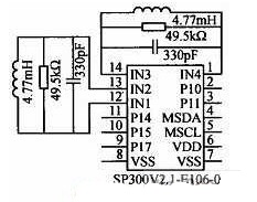
Figure 3 low frequency hardware schematic
The shunt resistor R mainly reduces the quality factor Q of the LCD resonant circuit to a low frequency sufficient bandwidth (7.8 kHz).
Resonant circuit quality factor
This requires that the LF resonant circuit quality factor Q cannot be greater than 15. The resistance R = Q × XL = 15 × 2π × fc × L = 49.5 kΩ can be calculated.
Since the SP300V2.1-E106-0 low frequency wake-up and receive baud rate hardware is set to 3.9 kbps Manchester encoding. Figure 4 shows the relationship between low frequency carrier data transmission and Manchester coding.
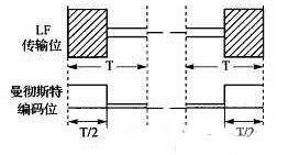
Figure 4 Relationship between low frequency carrier data transmission and Manchester coding
Since the hardware has been solidified to a 3.9 kbps Manchus* baud rate, each transmit bit time calculated by LF is 3.9 kbps x 2 = 7.8 kbps.
3 antenna design
The performance of the antenna will directly affect the quality of the data transmission, which is an important factor in the increase of the transmission power of the vehicle tire monitoring sensor. The antenna of the automobile tire monitoring sensor is close to the valve. Therefore, when designing the antenna, the shielding of the tire wire must be considered, the reflection effect of the rim metal, and the influence of the antenna changing direction and angle when the wheel rotates at a high speed, etc., so the antenna design must be considered. The following factors: polarization selection, linear polarization is easily affected by the attitude of the antenna, the rotating wheel has relatively high requirements for the working polarization of the antenna; the connection between the antenna and the RF module needs to solve the problem of impedance matching, which is also the antenna design. Focus; because the tire pressure sensor is installed in the tire, it is affected by the performance of the body and antenna movement, mainly refers to the influence of the gain, pattern shape, impedance (resistance and reactance) of the antenna; miniaturized design, installed in The antenna inside the tire must be considered for miniaturization. The operating frequency of 433.92MHz and the wavelength is 691.37 mm. The conventional antenna size must not meet the requirements.
Based on the above considerations, the valve is selected as the antenna of the transmitting module. The antenna has the advantages of easy processing, low cost, easy integration design and easy matching.
The valve antenna is a commonly used antenna form for automobile tire monitoring sensors at home and abroad. It belongs to the category of small electric antennas. The design of electric small antennas focuses on the design of the structure size and the setting of the matching circuit. Because the radiation resistance of the small antenna is generally small (several Ω), the radiation efficiency of the small antenna is generally low, and there is often an imaginary part in the radiation impedance, and this energy storage factor will further reduce the radiation efficiency. The imaginary part can be solved by the matching circuit, but the real part resistance needs to match the impedance of the RF output pin of the transmitting chip, which is also the design focus of the transmitting small antenna. The antenna loading mode adopted in this solution is loaded by an internal matching brass piece, which is similar to the inverted F antenna loading mode, as shown in FIG. After the bench test and road test, our design ideas and matching methods are effective.
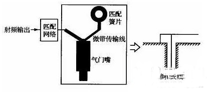
Figure 5 Schematic diagram of the valve antenna and equivalent inverted F antenna
4 software design
The system has software functions: periodic measurement of tire pressure, temperature value, variable periodic launch tire pressure, temperature value, BCM low frequency RF data receiving processing, high pressure alarm function, low air pressure alarm function, high temperature alarm function, fast leak Air alarm function, battery voltage low alarm function, sensor no signal alarm function. The system requires 10 years of life characteristics, the system has to achieve such a long service life, the system is in a sleep state under normal conditions, the quiescent current is only 0.66A, the system sleep state can be awakened by low frequency LF interrupt or timer interrupt. The system software framework process is shown in Figure 6.
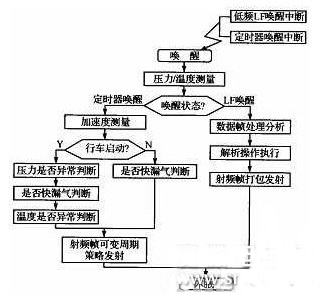
Figure 6 system software framework process
SP300V2.1-E106-0 internal ROM comes with the underlying library function (Library Function), the user can directly call the library function.
Since the tire pressure sensor installed inside each tire of the vehicle may have the possibility of simultaneous high-frequency data transmission, radio frequency interference will occur between the data during this period, and the BCM controller RF receiving end cannot receive the correct data, that is, Data conflicts. Data conflicts are randomly generated and cannot be avoided, but data collisions must occur again after a conflict has occurred.
The probability is as low as possible to avoid continuous data conflicts. At present, the system adopts a random delay between each transmitted high frequency data frame, and the random delay time is the prime multiple of the data frame time length, and the system selects 3 times, 5 times, 7 times, 11 times and 13 times. Times. Thus, if there is a data collision in the previous module, the data collision will only occur again when the random delay time of the module transmitting the conflict is the same, the probability is 4%.
5 structural design
The tire pressure sensor is mounted inside the car tire and consists of a valve, a housing and a dust cap. The driving speed of the car can reach up to 250 km/h, and the internal environment of the tire is complex and extremely bad. It is in the environment of high pressure, high humidity, alternating temperature, oil pollution, bumpy vibration, etc., and the temperature changes easily make the casing embrittlement and make The mechanical strength is reduced. In high-humidity conditions, the shell will expand, the strength will decrease, and the chemical reaction such as corrosion will occur. The tires will travel on various road surfaces, and the vibration frequency ranges will vary. These conditions may lead to loose parts. Take off. This requires the system structure design to consider the following points: system total weight requirements are light (less than 40 g), high speed resistance, high structural fracture strength, high sealing (IP6 protection rating), structural and valve material selection resistance High and low temperature and corrosion resistant materials, anti-loose design at the joint between the valve and the rim.
6 Conclusion
Whether it is bench test or road test in various situations, the tire pressure sensor maintains high reliability, and the system low-frequency transmission accuracy and high-frequency transmission and reception accuracy rate reaches 98%. When the tire is in an abnormally dangerous situation, the car dashboard displays relevant alarm information, prompting the driver in real time, eliminating the accident caused by the tire pressure problem in the bud, and enhancing the safety of the vehicle.
24W Wall Mounted Power Adapter
12V 2A power adapter is a versatile and essential tool for powering a wide range of electronic devices. With an output of 12 volts and 2 amps, this ac adapter is capable of providing reliable and stable power to devices such as routers, modems, LED light strips, and many other gadgets.
This dc12v 2a switching power adapter is compact and lightweight, making it easy to transport and use in various settings. It features a standard plug that fits into most outlets, allowing for quick and convenient setup. The 12v 2a adapter also comes with built-in protection mechanisms to prevent overloading, overheating, and short circuits, ensuring the safety of both the device and the user.
Whether you need to power up your home office equipment, charge your portable devices, or run your LED lighting setup, the 12V 2A ac dc power adapter is a reliable and efficient solution. Its high efficiency and low energy consumption make it an environmentally friendly choice, while its durable construction ensures long-lasting performance.
Overall, the 12V 2A power adapter is a versatile and dependable accessory that provides the necessary power for a variety of electronic devices. Its compact size, safety features, and efficiency make it an ideal choice for anyone in need of a reliable power source.
12v 2a switching power adapter, 12v 1.5a adapter, 9v 2a adapter, 24v 1a ac adapter
Guangdong Mingxin Power Technologies Co.,Ltd. , https://www.mxpowersupply.com