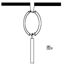
The input characteristic impedance of a general receiving device (such as a TV) is 75Ω (unbalanced) or 300Ω balanced, and the output of the half-wave symmetrical vibrator is: the impedance is 75Ω balanced.If you are connected to a 300Ω balanced cable, you only need to consider the impedance It is enough to match.We can use the special property that the equivalent impedance at the odd multiple of λ / 4 from the terminal on the transmission line is equal to the square of the characteristic impedance of the transmission line divided by the terminal load to perform impedance matching.The mathematical expression of this characteristic is Zin = Z0 * Z0 / ZL, where Z0 is the characteristic impedance of the transmission line (matching cable), Zin is the output impedance of the antenna, ZL is the impedance of the load (input impedance of the receiving device), and the calculation of the connection between the half-wave symmetrical oscillator and the 300Ω parallel cable As follows: First calculate the characteristic impedance of the required cable according to the above formula
Half-wave folded oscillator

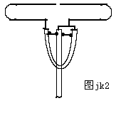
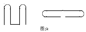
 In practical use, the folded oscillator antenna is generally used in the form of a folded oscillator.The main purpose is to increase the bandwidth of the antenna.The structure of the folded oscillator is shown in Figure jk.The frequency band characteristics of this antenna can be proved in this way. : As a dipole antenna, the folded dipole can be regarded as two λ / 4 short-circuit lines connected in series. For the resonance frequency wavelength L = λ / 4, neither the dipole antenna nor the short-circuit line has a reactance component. When the frequency of the high-frequency current on the equivalent oscillator changes within a certain range, the following two situations occur: when the frequency is higher than the resonance frequency, which is equivalent to L> λ / 4, the dipole antenna is approximately longer than the short-circuit line of λ / 4, and its reactance It is inductive, and the reactance of the short-circuit line at this time is capacitive. When the frequency is lower than the resonance frequency, it is equivalent to L <λ / 4. The dipole antenna is similar to the open path of λ / 4, and its reactance is capacitive. The reactance on the time-short line is also inductive; therefore, when the operating frequency is shifted, the inductive and capacitive reactances on the folded oscillator can compensate each other within a certain frequency range, so that the antenna has its impedance in a wide frequency range The characteristics do not change much. This is the principle that the folded oscillator has a wider frequency band. Since the two parallel conductors of the folded vibrator have the same phase and equal current (that is, I1 = I2), the radiation current is I = I1 + I2 = 2I1, and the radiation power is P = I * I * Rr = (2I1) * ( 2I1) * Rr (Rr is the input impedance of the half-wave oscillator) input power at the feed end of the folded oscillator P = 4 * I1 * I1 * Rr = (Rin is the input impedance of the folded oscillator) due to the current input at the feed end It is actually I, so I = I1, so Rin = 4Rr = 4 × 73.1 = 300Ω Here we get the input impedance of the folded oscillator is 300Ω. It is 4 times the input impedance of the symmetric half-wave oscillator. In order to solve the connection between the 75Ω coaxial cable and the antenna element, a phase made of a coaxial wire with a length of λ / 2, an impedance transformation device, commonly called a U-shaped ring, can solve the above two problems. The structure diagram of jk2 is shown below.
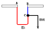
 It can be seen from the figure that after feeding, the current at point B passes through the U-shaped ring, and the current phase difference from point A is π (180 degrees) .The outer conductor of the U-shaped ring forms a short-circuit line of λ / 4, so that at A, B The impedance at the point is infinite, so the current on the outer conductor will not flow from the inner surface wall to the outer surface wall to ground, and the U-shaped ring also plays a role in impedance transformation.If the input current is on the coaxial core line Is I1 and the input voltage is V1, then the input currents on the two antenna elements of the antenna are I1, and the outer conductor of the coaxial line is grounded, so the voltages of the two points A and B to the ground are V1, and A and B are both The point voltage is reversed, so the voltage between the two points A and B is VA + VB = 2V1, and the impedance presented at the feed point is: R == 4V1 / I1, that is, after the U-shaped ring is used, the feed line and the antenna contact point The impedance has been increased by four times.If the coaxial cable with a characteristic impedance of 75Ω is used for feeding, the impedance at the feeding point is 75Ω × 4 = 300Ω, which can achieve a better match with the equivalent.

Follow WeChat
Interesting and informative information and technical dry goods

Download Audiophile APP
Create your own personal electronic circle

Follow the audiophile class
Lock the latest course activities and technical live broadcast
comment
Publish
related suggestion
Analysis of matched connection of half-wave symmetrical oscillator 
Analysis of matched connection of half-wave symmetrical oscillators ...
Posted at 2006-04-16 20:04 • 531 views
