With the rapid growth of standby energy consumption of electrical products, the family and society have paid too much. The survey conducted by China Energy Conservation Certification Center on household standby energy consumption shows that standby energy consumption accounts for about 10% of household electricity consumption. Taking the TV as an example, the average standby energy consumption of each TV set is 8.07W, which consumes about 0.016 degrees of power for 2 hours per day. The resource and environmental problems caused by standby energy consumption are receiving more and more attention from the society. For this reason, the International Energy Agency has proposed a “1 watt plan†to implement a 1 watt standby energy consumption action by 2010. The plan received positive response from the EU and the United States, and signed an agreement to reduce standby energy consumption year by year. Countries have successively introduced mandatory regulations (for example, the European Commission officially launched the “European Smart Source Program†in 2003, and the EU published in June 2005. The Green Paper on Energy Efficiency, the United States implemented the "white label mechanism" in 2006. Because of its convenience and energy saving, the intelligent switch socket has been widely welcomed by foreign consumers. At present, the intelligent switch socket is becoming a research hotspot of new energy-saving products.
The infrared remote control energy-saving switch socket is an intelligent switch socket designed for the TV set adopting EU technical standards. This paper describes the hardware circuit design, software algorithm design and white/black box stereotype test of the infrared energy-saving switch socket. The design and finalization scheme of the automatic switch socket is given. The consumer can use it to automatically control the electric appliances in the home that need to be continuously switched without the need to unplug the plug.
1 Infrared energy-saving switch socket hardware design
1.1 Working principle of infrared energy-saving switch socket Infrared energy-saving switch socket refers to the equipment that uses the infrared light to make the switch socket open or close within the specified space distance, and automatically disconnects the power after a certain time delay.
The external energy-saving switch socket has an automatic power-off function, which mainly uses the input voltage of the load to work in a large difference between the effective waveforms in the standby state and the power-on state. The effective waveform taken by the load in the standby state refers to the absolute value greater than the threshold portion in one cycle; the effective waveform portion taken by the load device in the power-on state means that the waveform direction is the same as the standby state in one cycle. The absolute value is greater than the size of the threshold portion.
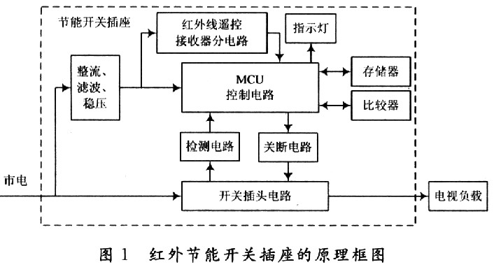
Let the half of the peak-to-peak value of the TV load input voltage waveform be the threshold of the waveform. If the absolute value is greater than the threshold, it is considered to be high level; if the absolute value is less than the threshold, it is considered to be low level. In the standby state or the power-on state of the TV, the input voltage waveform is in a single cycle, and the absolute value is greater than the threshold. The ratio of the waveform is usually above 1:2, so that the load input voltage waveform can be sampled by the sampling circuit, and the sampled value is The MCU memory can also be represented as binary data. Therefore, the schematic diagram of designing the infrared energy-saving switch socket is shown in Fig. 1. It is a smart switch socket composed of MCU control circuit, detection circuit, comparison circuit, shutdown circuit, infrared receiving circuit, switch plug circuit and power supply circuit. .
This article refers to the address: http://
1.2 Design of the detection circuit In the hardware circuit design of the infrared energy-saving switch socket, the detection circuit is responsible for detecting the voltage waveform of the input end of the load TV in different states, and sending the sampled waveform data to the post-stage amplification circuit. The amplified waveform data is then analyzed and processed by the comparison circuit and the single chip microcomputer. The circuit schematic diagram of the detection circuit is shown in FIG. 2 .
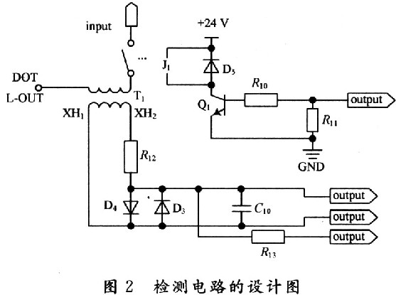
The coil is an important device for sampling the load input voltage waveform. According to the electromagnetic theory, the coil edge fringing field is ignored, and if the center is a uniform magnetic field, the number of turns of the detecting circuit coil calculated by the equation (1) is [O. 5,5]åŒ. ![]()
Where: N is the number of turns of the coil (unit: åŒ); B is the magnetic induction intensity of the center of the tube (unit: G); l is the effective length of the deflection yoke (unit: cm); I is the current flowing through the coil (unit: A); β is the angle between the center point of the deflection yoke axis and the diameter of the deflection yoke.
Generally speaking, the number of turns of the coil is proportional to the voltage. Decreasing the number of turns of the coil contributes to the sampling of the voltage waveform, which is not conducive to the stability of the voltage waveform. Increasing the number of turns of the coil can improve the sampling stability of the voltage waveform to a certain extent. , but the sampling accuracy will be reduced. In order to accurately determine the number of turns of the detection circuit coil from the estimated value, it is necessary to test the number of turns of the switch socket to find the optimum number of turns of the coil.
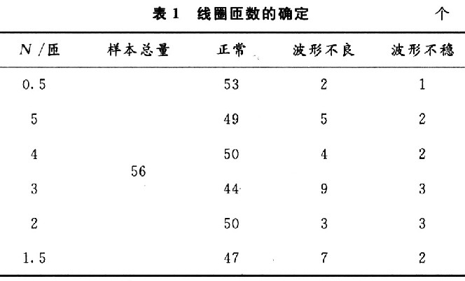
In the trial production of batch products, 56 semi-finished products were randomly selected as test pieces, and the actual measurement plan was designed to complete the evaluation of the inductance coil turns. First, proceed with O. 5 åŒ coil test, if the indicator is not met, the coil turns are directly adjusted to the maximum value of 5 åŒ and then tested. If the performance index still does not meet the design requirements, test the number of coil turns on a 1åŒ basis until it is reduced to 2åŒ (including 2åŒ). If the design requirements are still not met, the reduced base is changed to 0.5 åŒ, that is, the test is performed with a 1.5 线圈 coil. According to the above test scheme, the coil turns of 0.5åŒ are selected first, and the test results show that the waveform is good, the product has a good rate of 94.6%; the standby or start-up waveform has two bad ones, and the waveform is unstable. One. The test of 5 åŒ, 4 åŒ, 3 åŒ, 2 åŒ and 1.5 åŒ coils was carried out in the same manner, and the data shown in Table 1 was measured. The product excellent rate was 87.5%, 89.3%, 78. 6%, 89.3% and 83.9%, it can be seen that the product with the coil N=0.5åŒ has the best performance.
1.3 Comparison circuit design The comparison circuit of the infrared energy-saving switch socket is responsible for comparing and comparing the sampled standby waveform and the working waveform. It is the key circuit for the switch socket to complete the automatic shutdown function. The circuit schematic design is shown in Figure 3. Shown.
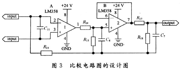
It can be seen from the circuit diagram that the LM358 amplifier is the core device of the comparison circuit. The LM358 is a low-power device suitable for battery power. It has two independent, high-gain, internal frequency-compensated dual operational amplifiers. The two LM358s can be used to convert the current signal of the input coil into a bipolar voltage signal output, which can be used for comparison between the standby waveform and the real-time sampled waveform data in the memory controlled by the single chip microcomputer.
In order to verify the actual effect of the comparison circuit design, the number of turns from the coil is O. 50 test pieces were randomly selected from the 5 åŠ semi-finished products for testing.
In the first step, if the power-on/standby waveforms are all good, the numbers are classified into the normal waveform class. If the power-on/standby waveform is not good, the number will be changed after the LM358 is replaced. If the waveform is good, it will be classified as normal after replacing the LM358. If the waveform is still bad, it will be classified into other faults and get the test as shown in Table 2. data. For the first two types of semi-finished products, after the whole machine is installed, the second step test is carried out; for the third type of semi-finished products, the maintenance department diagnoses the fault and repairs, and no further testing is performed.
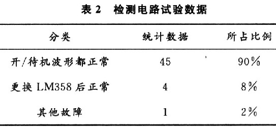
In the second step, the 49 semi-finished products with the normal waveform of the previous step are installed into the whole machine for functional verification. The observation time of the detection process, the automatic power-off process, and the use of the TV set are 3 min, 1 min, and 10 min, respectively. If the first two exceed the above assumptions, they will be classified according to different reasons. The test obtained 44 normal, 5 functions are not good, of which 5 of the poor functions include 2 automatic shutdown at boot; 3 can not automatically power off after 10 minutes of standby using the remote control (automatic power off) Test results of process failure). After the fault detection and isolation, it was found that the two complete machines that were automatically shut down at startup were caused by the coil and the circuit board being soldered. After repairing, the three machines were not automatically powered off for 10 minutes. One of them was found. It is a mistest, and the other two belong to the good waveform class after replacing the LM358. Therefore, it can be said that after randomly sampling 50 semi-finished products into a complete machine, regardless of the PCB board welding failure and the reliability of the LM358 components themselves, there are 49 qualified products, and the pass rate is over 98%, indicating that the circuit is Design meets design requirements.
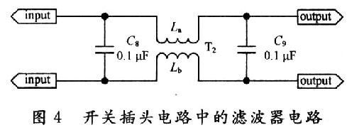
1. 4 EMC design of switch plug circuit The requirements of electromagnetic compatibility of products in developed countries are generally high. In order to meet the needs of exporting infrared energy-saving switch sockets, the switch plug circuit design has electromagnetic interference suppression circuit. The electromagnetic interference suppression part of the switch plug circuit uses a common mode inductor and a capacitor in series to form a noise filter circuit. As shown in FIG. 4, two sets of low-pass filters composed of C8, La, and C9 and Lb can be made on the line. The electromagnetic interference signal is controlled at a prescribed level. The noise filter can effectively suppress the electromagnetic interference signal of the external power grid from entering the load television through the switch socket, enhance the viewing effect of the television, and can also attenuate the electromagnetic interference signal generated by the load television to pollute the external power grid, and satisfy the infrared energy-saving switch socket. The original intention of EMC design.
2 Infrared energy-saving switch socket software design The design of infrared energy-saving switch socket control software not only considers the practicability of the software, but also takes into account the reliability of the code, and carries out the three-way test of the system. The software design as a whole can be divided into system management main program, system call subroutine, power-on self-test subroutine, detection process sub-program, automatic electronic break program, delay sub-program, alarm sub-program and system protection sub-program.
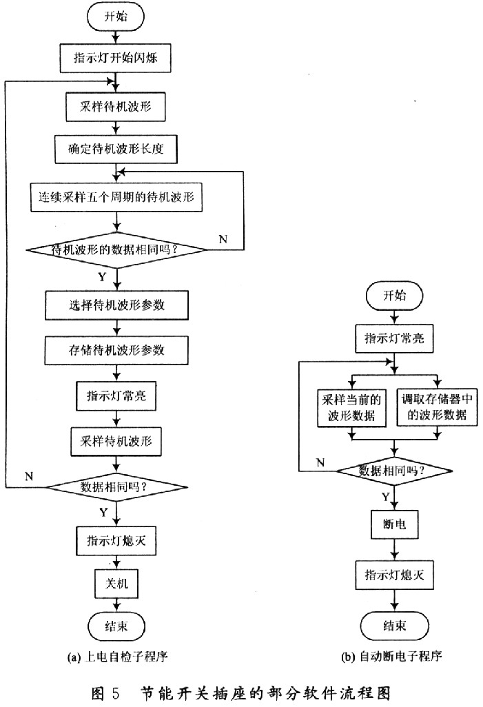
In the first time, the infrared energy-saving switch socket needs to be powered on and detected. First, plug the TV power plug into the switch socket, then plug the infrared switch socket into the external power socket, and then set the TV with the remote control. In standby mode. At this time, the infrared energy-saving switch socket will flash the indicator light to indicate the power-on self-test process of the system. The software flow is shown in Figure 5(a). At this point, the switch socket will sample, identify, and store the waveform in which the TV is in standby. During the flashing of the indicator light, the detection circuit samples the standby waveform; if the sampling waveforms of the five consecutive cycles are identical, the identification of the standby waveform is completed by the blinking of the indicator light; after the indicator light is in the steady state, the single chip microcomputer will This waveform is recorded as the standby waveform of the TV. Then wait for a while, if the load TV is not working at all, the waveform detected by the system is consistent with the waveform in the memory, and the shutdown circuit cuts off the external power.
The remote control of the TV and the infrared energy-saving switch socket is compatible with each other. The user can turn on the switch socket with the TV remote control, and then turn on the TV with the remote control. When the TV is in the normal power-on state, the audio-visual functions such as image and sound are simultaneously turned on, so that the power consumption of the TV is increased. At this time, the waveform detected by the detection circuit and the standby waveform recorded in the memory are greatly different. The main program, system call subroutine, detection process subroutine, alarm subroutine and system protection subroutine are all running normally, which ensures that the TV will not automatically shut down under such circumstances. Users can watch TV programs normally, which is also a basic function that energy-saving switch sockets must have.
The user turns off the TV with the remote control, and after the TV is in the standby state, the automatic electronic shutdown program starts running. The flow chart is shown in Figure 5(b), when the waveform at the moment is detected and the standby waveform recorded in the memory is detected. When they are consistent, the MCU will control the power off to ensure that the TV can be completely shut down after the user finishes using it, thus saving standby power consumption.
In the future use, if the TV plug is not pulled out from the infrared energy-saving switch socket, and the infrared energy-saving switch socket is not pulled out from the power supply, the standby state can be automatically turned off, and the TV can be saved to the utmost. Standby energy consumption.
3 infrared energy-saving switch socket stereotype test
3.1 White box test of infrared energy-saving switch From the working principle of the intelligent switch socket, it can be known that the detection circuit can sample a good standby waveform, which is the premise of whether the design of the infrared energy-saving switch socket is successful; whether the comparison circuit can clearly distinguish the standby state and The waveform of the working state is the basis for whether the infrared energy-saving switch socket can realize automatic shutdown. Visible detection circuit and comparison circuit are the key circuits of automatic switch socket. White box test is to test these two circuits.
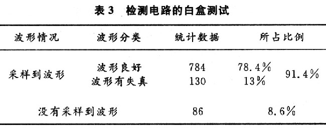
Firstly, the board is tested on the test rack. After the test is passed, 1 000 boards are randomly selected as samples for the white box test. The white box test of the detection circuit is divided into two types: the acquired and the non-advanced standby waveform. In this case, the sampled standby waveform is divided into two cases: the waveform is good and the waveform is distorted. The specific test data is shown in Table 3.
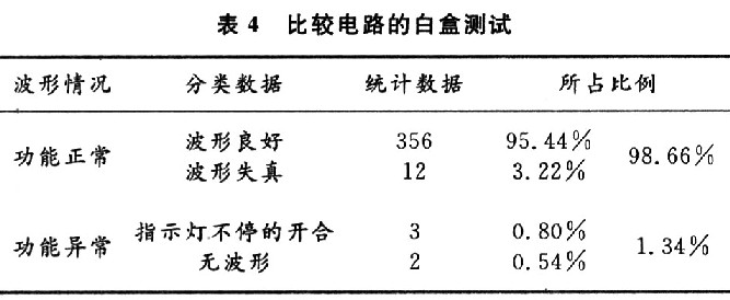
For the semi-finished products that passed the white box test in the previous step, 373 test pieces were extracted therefrom, and the comparison circuit was subjected to a white box test to obtain data as shown in Table 4. It can be seen from the measured data that the white box test pass rate of the infrared energy-saving switch socket semi-finished product is 98.66%, so the batch meets the mass production requirements.
3.2 Black box test of infrared energy-saving switch Before the product of infrared energy-saving switch socket is finalized, it is necessary to carry out black box test of the whole machine function to verify its energy-saving function. According to the use environment of the infrared energy-saving switch socket, the severity level of the test can be divided into two situations: first, the load television has no closed-circuit signal and sound, and the high severity level function test under the blue screen state; second, the load television The audiovisual signals are all turned on, and the user enjoys the low severity level function test under the program state.
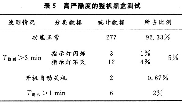
During the black box test, the TV set life is specified as 5 min. From the infrared energy-saving switch sockets that passed the white box test, 300 semi-finished test pieces were randomly selected and installed as a whole machine for black box function test. In the first case, 300 infrared energy-saving switch socket test pieces were tested to obtain 277 normal test pieces, and 15 test times were more than three minutes (including 3 indicators flashing all the time and 12 in the test phase three). In the minute, the indicator light does not go out. 2 auto-shutdowns are turned off, and 6 of them can't be automatically powered off within 1 min. There are 23 malfunctions, as shown in Table 5.
For the 23 problem specimens found above, the black box test in the second case was carried out. The test data is shown in Table 6, and 15 machines with a detection time of more than 3 min were obtained. The test was qualified under the condition; and two test pieces with serious failure phenomenon of automatic shutdown were placed on the optional three different load televisions for testing, one of which was automatically de-energized while the other was found to be the circuit. One of the resistors in the comparison circuit on the board is damaged. After the replacement, the test function is normal. If the 6 automatic power-off times are longer than 1 min, there are 2 power-off times longer, and the other 4 have closed-circuit signals in the TV. All are qualified under the conditions.
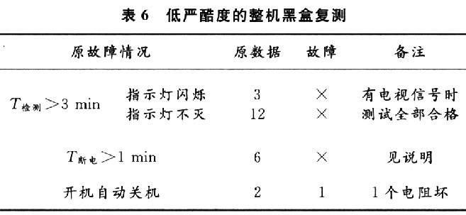
In summary, 300 infrared remote control energy-saving switch sockets for black box testing, 296 functions are completely normal, and the batch pass rate reaches 98.67%. There is also one circuit soldering fault and three automatic power-off times. In summary, the infrared energy-saving switch socket is designed to meet the requirements of formal mass production.
4 Conclusion Home appliances such as TVs waste a lot of energy in standby because they do not have timing control. The inherent energy-saving features of the infrared energy-saving switch socket realize the function of “automatically unplugging the plug when the user does not use it and automatically plugging it when using itâ€, which can set the power-off and power-on time irregularly, achieving easy operation and energy saving. The purpose has played an important role in promoting a conservation-oriented society. The infrared energy-saving switch socket has the advantages of high reliability, long life, low power consumption, fast response, etc., so that even in the current global financial crisis, it has won the favor of users in Germany, Britain, Australia and other countries, only 2008 In the second half of the year, it received about 46,000 orders.
Outdoor Power Supply,Solar Lithium Battery,Portable Rechargeable Lantern,Power Solar Station Equipment
Sichuan Liwang New Energy Technology Co. , https://www.myliwang.com