Usually designing 110V EB is higher than 220V EB, especially for high power factor. Here are a few regular schematics to lead you into the topic of the article.
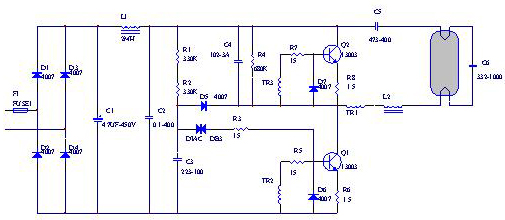
Figure 1 220V universal energy-saving lamp electronic ballast circuit diagram
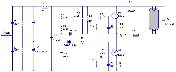
Figure 2 100-110V double voltage line
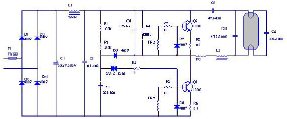
Figure 3 100-110V direct drive circuit diagram A
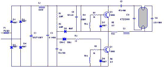
Figure 4 100-110V direct drive line A
Why is the 110V EB more difficult than the 220V EB? The most direct effect is the startup of the lamp. Especially when the whole lamp is at high temperature and low pressure, the lamp can not be successfully started, only the two sides are red. The reason is that the driving ability of the magnetic ring and the triode is lowered at a high temperature, so that the lamp starting voltage and the lamp starting current supply are insufficient to enable the lamp to be successfully ignited. Insufficient lamp start-up voltage and start-up current supply also affect lamp start-up at low temperature and low voltage. In addition, in order for EB to output the same power, the output current of 110V EB is naturally twice as large as the output current of 220V. The key point of output current control is the output inductor of EB (also called choke). The selection value is too large and the output power is insufficient. If the selection value is too small, the operating frequency of the EB will be seriously exceeded, and the switching loss of the triode will rise, leading to heat generation in the tube.
In the topology of the line, the above four schematics are the same, both are series resonant positive feedback circuits, but there are some clever places and different values ​​of components. The best working condition of this circuit must comply with:
Formula 1
Where: Fw is the working frequency. Fo is the natural frequency of the entire resonant circuit. The simple words are: the working frequency is equal to the natural frequency of the output inductor and the resonant capacitor, and the circuit can work in an optimal state. At this time, the load circuit is equivalent to a resistor, which can improve the efficiency of the entire EB and reduce the heat loss. The performance of the whole machine has increased.
Figure 1 is a conventional 220V schematic, and Figure 2 is a schematic diagram of 110V doubled. Figure 3 is a schematic diagram of direct drive of a 110V double resonant capacitor, and Figure 4 is a schematic diagram of direct drive of a double resonant capacitor and a filament.
Figure 1 is not suitable for use in the 110 circuit. What is the solution? Because to maintain the determined power, the output inductor L2 must be chosen to be small. To meet the above formula, the resonant capacitor C6 will be selected to be large, and the C6 cannot be selected too. Large, because it is too large, the starting voltage will decrease. The reason is: a high-frequency current flows through the filament, C6 increases, the resistance equivalent to C6 decreases, the voltage across C6 drops, the output inductor and the voltage drop of the filament rise, and the voltage across C6 drops, equal to the lamp. When the tube voltage drops, it is easy to cause the high temperature failure problem described above.
Because of this, people have studied the voltage doubler rectifier circuit shown in Figure 2, D1, D1, C1 constitute a voltage doubler full-wave rectification filter circuit, the rectified and filtered voltage can be expressed by the following formula:
Equation 2
Where: Vo is the output DC voltage and Vin is the input AC voltage. The disadvantage of this circuit is that it is difficult to be used in the circuit above 120V, such as the 127V electronic energy-saving lamp. The reason? You can calculate the 120V energy-saving lamp according to the above formula, and supply the 132V AC voltage in the positive 110% voltage environment. How high is the voltage after the rectification and filtering, and the triode with a small difference in pressure is acceptable? It is also necessary to remind you that the maximum withstand voltage of the triode at high temperature is slightly lower than the normal temperature withstand voltage. When the supply voltage exceeds the maximum withstand voltage of the triode, the diode will have a second breakdown, causing a short between the collector and the emitter.
In Figure 3, the compensation capacitor C0 is added to Figure 1, which can effectively conform to the resonance formula (Equation 1), which improves the efficiency of EB and greatly improves the startup performance. It is an ideal direct drive circuit. The magnetic ring material of this circuit should be a 2K or 2.5K material with a relatively flat BS temperature profile. The collector current Ic and the amplification factor β of the triode are preferably larger. This circuit also has a big disadvantage. When the lamp is working for a certain period of time, the cathode of the lamp is completely aging, the filament is open, and the EB circuit still forms a series resonant positive feedback circuit due to the access of C0. The line still works, and the line power will be compared. It is twice as large as normal. If the EB is not damaged at this time, the two ends of the tube become red and the temperature is high, so that the plastic parts of the fixed tube can be dissolved.
Figure 4 is a more ideal direct drive circuit than Figure 3. The method of using a double resonant capacitor to cross the filament achieves better starting performance, and the operating frequency is closer to the natural frequency.
The rectified and filtered circuit of Figure 1 and Figure 2 does not require high current, and the supply voltage is high, so the negative feedback resistance (ie, the emitter resistance) can be selected to be larger. The 15W EB is used as an example. 2.2 ohms can be selected. of. However, the feedback resistors in Figures 3 and 4 are suitable for small points or even not directly used.
The selection of electrolytic capacitors must ensure that the current peak factor of the lamp is less than 1.7. The precondition for ensuring this parameter is to increase the capacity of the electrolytic capacitor. Increasing the capacity of the electrolytic capacitor will lead to an increase in the total harmonic of the input current. Some countries or regions It is required for the total harmonic of the current. For example, in Taiwan of China, the total harmonic of the input current of the energy-saving lamp cannot be higher than 120%. Sometimes, in order to make both meet the requirements, a 3-10 Ω series is usually connected in series at the input end of the power supply. High-power wirewound resistors increase the resistive load to reduce the total harmonics of the current. The resistance of this resistor should not be too large, so as to avoid excessive heat dissipation and severe heat generation. Also, carbon film resistors cannot be used because the ability of carbon film resistors to resist current surges is not ideal.
The relationship between the magnetic ring pulse transformer and the load circuit, in terms of problems, please look at the following picture:
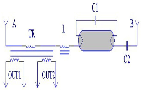
Figure 5
In Figure 5: A and B are high-frequency input terminals, TR is a magnetic ring pulse transformer, L is the output inductor, C1 is the resonant capacitor, C2 is the DC blocking capacitor, and OUT1 and OUT2 are the driving sources of the triode. They form a complete LC series circuit.
Let us first discuss the effect of the number of primary turns and the number of secondary turns on the output voltage. From a very surface, according to the ratio of the transformer:
It can be said that the smaller the number of primary turns, the more the number of secondary turns, the higher the output voltage. The above concept is justified. Don't neglect that the primary coil is connected in series with the output inductor L, the resonant capacitor C1, and the DC blocking capacitor C2. The smaller the number of primary turns, the smaller the equivalent resistance of the loop. The smaller the voltage drop, the lower the voltage it gets in the loop and the smaller the output. The relationship between the number of turns of the TR primary and the output inductor L is as follows: the output inductance L is large, the number of turns of the primary ring of the magnetic ring pulse transformer is large, the output inductance L is small, and the number of turns of the primary ring of the magnetic ring pulse transformer is small. However, the output voltage should meet the driving requirements of the triode, and the voltage should not be under-excited, so that the triode does not work in the amplification region, and the excitation cannot be over-excited. This makes the delay time too long, increases the switching loss, the tube heats up, and the common state is more serious. Turn on and burn the triode. For detailed drive parameters, please refer to the data sheet of the triode you are using.
The 110V direct drive line also has strict requirements on the material of the magnetic ring. It is generally suitable to use a low permeability material such as 2K or 2.5K which does not change much with temperature. In the figure below, Figure A is ideal.
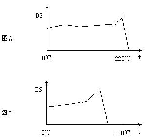
Figure 6
The requirement of the 110V direct drive line for the triode is mainly that the collector current Ic must have sufficient margin to ensure that the lamp can provide sufficient starting current at high temperature to make the lamp ignite successfully. In addition, the magnification is preferably larger (such as β = 25-35), and the withstand voltage is greater than 300V.
The working frequency, with our current bipolar transistor on hand, 28-40KHz is the most suitable. Also depends on the safety certification requirements of Energy Star and other countries.
Overall, the main point of the 110V energy-saving lamp EB design is the activation of the lamp and the resonance adaptation of the lamp. The specific setting also requires you to make appropriate adjustments in the actual operation. The quality of other components must pass.
ZGAR AZ BOX Vape
ZGAR electronic cigarette uses high-tech R&D, food grade disposable pod device and high-quality raw material. All package designs are Original IP. Our designer team is from Hong Kong. We have very high requirements for product quality, flavors taste and packaging design. The E-liquid is imported, materials are food grade, and assembly plant is medical-grade dust-free workshops.
Our products include disposable e-cigarettes, rechargeable e-cigarettes, rechargreable disposable vape pen, and various of flavors of cigarette cartridges. From 600puffs to 5000puffs, ZGAR bar Disposable offer high-tech R&D, E-cigarette improves battery capacity, We offer various of flavors and support customization. And printing designs can be customized. We have our own professional team and competitive quotations for any OEM or ODM works.
We supply OEM rechargeable disposable vape pen,OEM disposable electronic cigarette,ODM disposable vape pen,ODM disposable electronic cigarette,OEM/ODM vape pen e-cigarette,OEM/ODM atomizer device.


ZGAR AZ BOX Vape,ZGAR AZ BOX disposable electronic cigarette,ZGAR AZ BOX Vape vape pen atomizer , AZ BOX Device E-cig,AZ BOX disposable electronic cigarette
ZGAR INTERNATIONAL(HK)CO., LIMITED , https://www.zgarecigarette.com