For insulation resistance between certain contacts of electronic equipment or multi-core cables, it is usually measured using a megohmmeter. The megohmmeter has a narrow measuring range (100 kΩ to 500 MΩ) and low precision (10% to 20%). The operation is complicated, especially for the measurement between multiple contacts.
This section designs a bridge zero measurement method, which uses a single-chip system to achieve wide range (20 kΩ to 1275 MΩ), high precision (error of ±2.5%) and automatic measurement (automatic switching range and automatic switching detection points). .
First, the measurement principle and system block diagram
1. Measuring principle
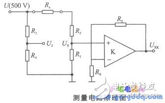
This system uses the bridge zero method to measure the insulation resistance when the applied voltage is 500 V. The circuit schematic is shown below.

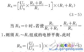
Available from the map:

When Rx is large, Ux is small. In order to ensure A/D conversion accuracy, Ux needs to be programmed and amplified. Set the amplifier output U XK, the magnification is K, then the formula (3-6) can be written as
Equation (3-7) is the mathematical model of the measurement. It can be seen from the model that the measured value of Rx is independent of the applied voltage U (500 V). When K, Ri and R2 are given, the bridge is balanced. Only U2 and UXK are measured, then the equation (3-7) ) The insulation resistance Rx can be obtained.
2. System Block Diagram
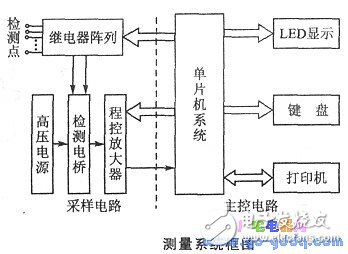
The measurement system consists of two main parts: the main control circuit and the sampling circuit. The figure below is its system block diagram. The main control circuit is a 8031 ​​single chip system. The sampling circuit consists of a relay array, a high voltage power supply detection bridge, and a programmable amplifier.

The system working process is: according to the key operation, the single chip system controls the relay array according to a given program, so that the detection point is connected to the Rx end of the measuring bridge; the high voltage power supply provides 500V DC voltage; the output voltage of the bridge is amplified by the programmable amplifier and A /D conversion, read by the MCU; Rx is calculated according to the formula (3-7), and the LED display or the printer prints the record.
Mining is the process of creating a block of transactions to be added to the Ethereum blockchain in Ethereum's now-deprecated proof-of-work architecture.
The word mining originates in the context of the gold analogy for cryptocurrencies. Gold or precious metals are scarce, so are digital tokens, and the only way to increase the total volume in a proof-of-work system is through mining. In proof-of-work Ethereum, the only mode of issuance was via mining. Unlike gold or precious metals however, Ethereum mining was also the way to secure the network by creating, verifying, publishing and propagating blocks in the blockchain.
Mining ether = Securing the Network
Mining is the lifeblood of any proof-of-work blockchain. Ethereum miners - computers running software - used their time and computation power to process transactions and produce blocks prior to the transition to proof-of-stake.
ETH Miner:Antminer E9 2.4Gh/S,Bitmain E9 2.4Gh/S,Bitmain Antminer E9 2.4Gh/S
Eth Miner ,Antminer E9 2.4Gh/S,Bitmain E9 2.4Gh/S,Bitmain Antminer E9 2.4Gh/S
Shenzhen YLHM Technology Co., Ltd. , https://www.ylhm-tech.com