Flow Control Flow Control is flow control. This concept originated in network communication. The purpose of using Flow Control on the PCIe bus is to ensure that the PCIe device at the sending end never sends a TLP (transaction layer packet) that the receiving PCIe device cannot receive. That is, the sending end can know whether the receiving end can receive the TLP to be sent through the Flow Control mechanism before sending.
In the PCI bus, there is no such mechanism as Flow Control, so the sender does not know the current time, and the receiver can receive the corresponding TLP. Therefore, the sender can only try to send first, during which multiple wait periods may be inserted (the receiving device is not yet ready, etc.), or even retransmissions.
PCIe Spec stipulates that each port of a PCIe device must support the Flow Control mechanism. Before sending a TLP, Flow Control must first check whether the receiving port has enough buffer space to receive this TLP. When a PCIe device supports multiple VCs (Virtual Channels), the flow control mechanism can significantly improve the bus transmission efficiency.
PCIe Spec stipulates that each PCIe device supports up to 8 VCs, and the Flow Control Buffer of each VC is completely independent. In other words, a VC's Flow Control Buffer is full and will not affect the communication of other VCs.
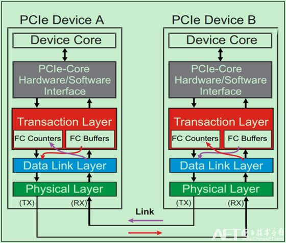
As mentioned in the previous article, the Flow Control mechanism is implemented by sending DLLP (Flow Control DLLPs) between the data link layers of two adjacent ports (Ports). During initialization, the receiving end needs to report the size of the Buffer to the sending end. In the normal running state (Run-time), the receiving end will periodically inform the sending end through the Flow Control DLLPs, and each Buffer of the receiving end. size.
It should be noted that although the Flow Control DLLP is only transmitted between adjacent data link layers, the related Buffer and Counter (FC Counter) do exist in the Transaction Layer. As shown below:

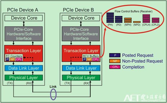
As mentioned in previous articles, there are three major categories of TLPs:
Posted Transactions (including Memory Writes and Messages), Non-Posted Transactions (including Memory Reads, Configuration Reads and Writes, IO Reads and Writes), and Completions (including Read and Write Completions). And know that TLP can be divided into two parts, Header and Data part. In order to achieve higher data transmission efficiency, Flow Control stores these three types of TLPs separately, and stores the header and data separately. Therefore, there are a total of six different Flow Control Buffer types, as shown in the following figure:

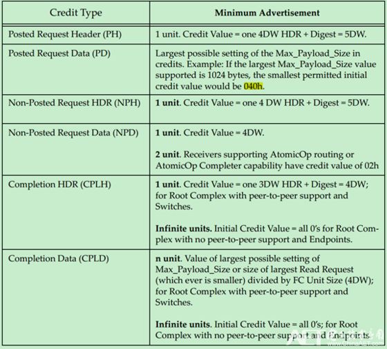
The Flow Control Buffer memory unit (Unit) is called Flow Control Credits. For the Header, the Requests TLP is equal to 5DW per unit and the Completions TLP is equal to 4DW per unit. For Data, each unit equals 4DW, which means that the Data Buffer is aligned to 16 bytes. The following table shows the minimum values ​​for various types of Buffers:

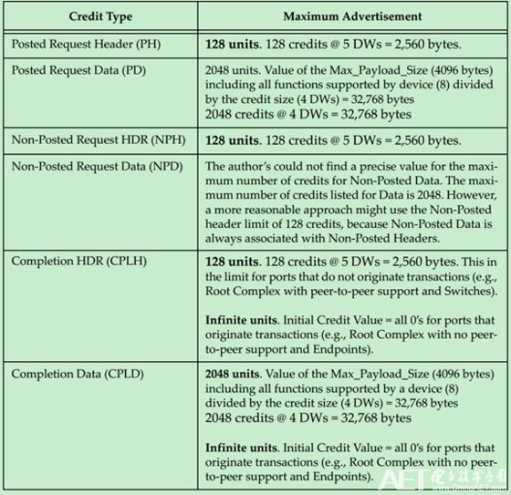
The maximum value is shown in the following table:

Note: 0 unit means Infinite.
ZTTEK Electric Scooter Batteries. Any size batteriesb can be customized! Suitable for most electric vechile modles, like electric e-bike, golf cart,forklift,beach electric motorcycle.
Electric Motorcycle Battery,Li-Ion Battery Pack For Electric Bike,Lithium Battery Charger For Electric Bike,Lithium Battery Pack For E-Bike
Jiangsu Zhitai New Energy Technology Co.,Ltd , https://www.zhitainewenergy.com