The drive circuit refers to the intermediate circuit between the main circuit and the control circuit that is used to amplify the signal of the control circuit (that is, the signal of the control circuit is amplified to enable it to drive the power transistor).
The influence of a good drive circuit on the performance of the converter:
1. Improve system reliability;
2. Improve conversion efficiency (switching device switching, conduction loss);
3. Reduce the stress of switching devices during the on/off process;
4. Reduce EMI or EMC.
The basic task of the drive circuit is to convert the signal from the information electronic circuit into a signal that can be added between the control terminal and the common terminal of the power electronic device to turn it on or off in accordance with the requirements of its control target. For semi-controlled devices, only the turn-on control signal is required, and for full-control devices, both the turn-on control signal and the turn-off control signal must be provided to ensure that the device is reliably turned on or off as required.
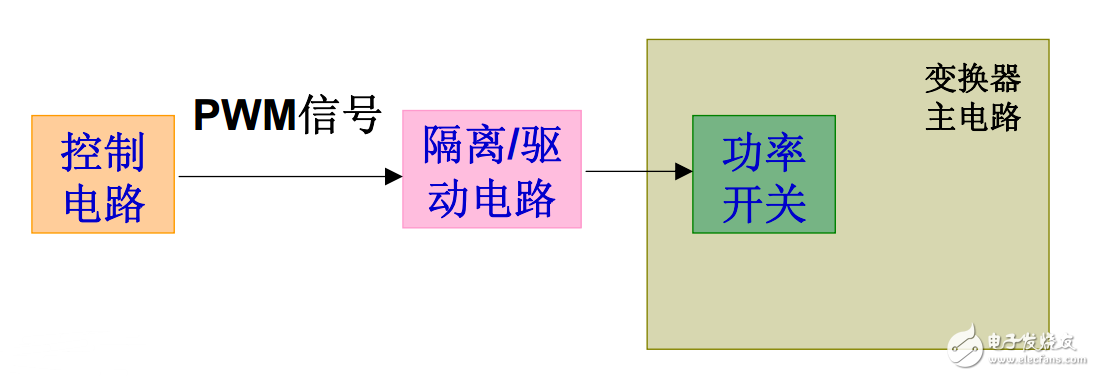
The essence of the drive circuit is to charge and discharge the gate capacitance.
The conditions for opening are:
1. The driving voltage is high enough, generally greater than 10 volts.
2. Sufficient transient drive current, fast rising edge, can accelerate the turn-on.
3. The impedance in the drive circuit is small.
The shutdown conditions are:
1. Sufficient transient drive current, fast falling edge.
2. The impedance in the drive circuit is large.
3. Drive plus negative pressure.
Drive circuit functionSimply put: the drive circuit is to amplify the PWM pulse output by the control circuit enough to drive the power transistor to switch power.
The drive circuit is essentially a power amplifier circuit to meet the rated power of the load so that the load can work normally, so that it can respond to weak input signals. Therefore, different loads need different drive circuits, but the essence is the same, such as LED Drive circuit, motor drive circuit, relay drive circuit, speaker drive circuit, etc.
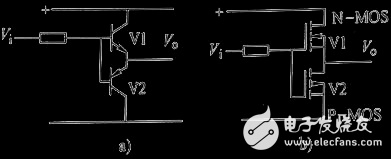
4 drive circuit diagramsNext, enumerate 4 drive circuit diagrams and carry out circuit analysis. Drive circuit 1. The drive circuit shown in Figure A is suitable for driving low-frequency and low-power IGBTs. When the control signal VI is high, V1 is turned on, and the switch tube corresponding to the output VO is turned on; when the control signal VI is low , V2 is turned on, and the switch tube corresponding to the output VO is turned off. The drive circuit shown in Figure B uses a field effect tube to form a push-pull circuit. Its working principle is the same as that in Figure A. The high-frequency peak drive current of this circuit can reach more than ten amperes, which is suitable for high-power switching devices.
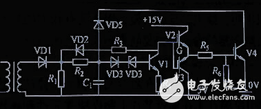
Drive circuit two. The driving protection two-in-one circuit as shown in the figure is suitable for driving low-frequency and low-power IGBTs. If the bipolar NPN and PNP transistors are replaced with N-channel and P-channel high-power field tubes, a high-frequency high-current driver can be formed . In the drive and protection two-in-one circuit, instead of using an optocoupler for signal isolation, a magnetic ring transformer is used to couple a square wave signal. Because the speed of the optocoupler is not fast enough, and there is a delay between the rising and falling edges of the optocoupler, it is adopted Transformer transmission can obtain steep rising and falling edges with almost no transmission delay. It is suitable for driving high frequency and high power IGBT devices. This circuit has fast driving speed and fast over-current protection action. It is an ideal driving protection two-in-one practical IGBT driving circuit.
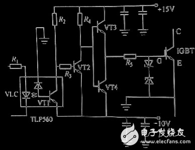
Drive circuit three. The driving circuit shown in the figure is an IGBT driving circuit composed of discrete components such as optocouplers. When the control signal is input, the optocoupler is turned on, the transistor VT2 is turned off, and VT3 is turned on to output a positive 15 volt driving voltage. When the input control signal is zero, VLC is turned off, VT2 and VT1 are turned on, and a negative 10 volt voltage is output. The positive 15 volt and negative 10 volt power supplies should be close to the drive circuit. The leads from the output terminal of the drive circuit and the power supply ground to the gate and emitter of the IGBT should be twisted-pair wires, preferably no more than 0.5 meters in length.
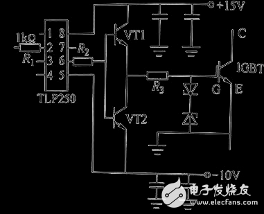
Drive circuit four. The drive circuit composed of integrated circuit TLP250 is shown in the figure above. The isolation voltage of TLP250's built-in optocoupler can reach 2500V, the rise and fall times are less than 0.5 microseconds, and the output current can reach 0.5A, which can directly drive IGBTs within 50A and 1200V. With the addition of push-pull amplifier transistors, IGBTs with larger current capacity can be driven. The driver composed of TLP250 is small in size and low in price. It is an ideal product among IGBT drivers without overcurrent protection. Because TLP250 does not have the overcurrent protection function, when the IGBT is overcurrent, the IGBT is turned off by the control signal, and the current in the IGBT drops very steeply, and there is a reverse impact. This will produce a large switching loss, and the overcurrent protection function of the control circuit is very demanding.
Servo Motor Cable Assembly
Servo motor cables have been developed for the quick connection of computer aided CNC machines as for example CNC mills or drilling machines. They combine current supply and data transmission perfectly. Motor connection cables, feedback cables as well as transmission cables belong to the servo motor cables. We provide a whole cable connectivity solution for CNC machine manufactories.
Further application fields of motor construction are more intelligent such as temperature control or industrial fields with intelligent servo drives. Our professional engineers will satisfy your unit custom needs with greatest patience.
Servo Motor Cable Assembly,Servo Harness,Servo Cable,Servo Motor Cable
Feyvan Electronics Technology Co., Ltd. , https://www.fv-cable-assembly.com