Due to the oil crisis and increasingly serious environmental pollution, the development of electric vehicles has become a general trend. The battery provides power for the electric vehicle, and the battery charging performance directly affects the use and life of the battery. The battery is generally divided into a lead battery, a nickel-cadmium battery, a nickel-metal hydride battery and a lithium-ion battery. Due to the large variety of batteries and different capacities, different types and capacities of batteries often require different chargers to match. If the battery charger does not match properly, overcharging, overheating, and other unsafe phenomena will occur, which will affect the normal use of the battery and shorten the battery. life. Therefore, it is very necessary to design a multi-functional charging system based on the single-chip microcomputer that can charge various types of batteries. The multi-functional charging system can quickly and stably charge different types and capacities of batteries. We have designed corresponding charging methods for different types of batteries in the software so that each type of battery can be charged under the optimal charging method. For batteries with different capacities, the battery can be quickly and stably charged by setting the charging parameters when selecting a good charging method.
1 Hardware circuit designThis system adopts a phase-shifted full-bridge soft-switching circuit, that is, a Boost circuit and a full-bridge converter are combined to form a single-stage PFC circuit. The circuit has a simple structure and high efficiency, and can realize the setting of input current and can also work at higher power. Occasionally, the advantages of full-bridge circuits are utilized.
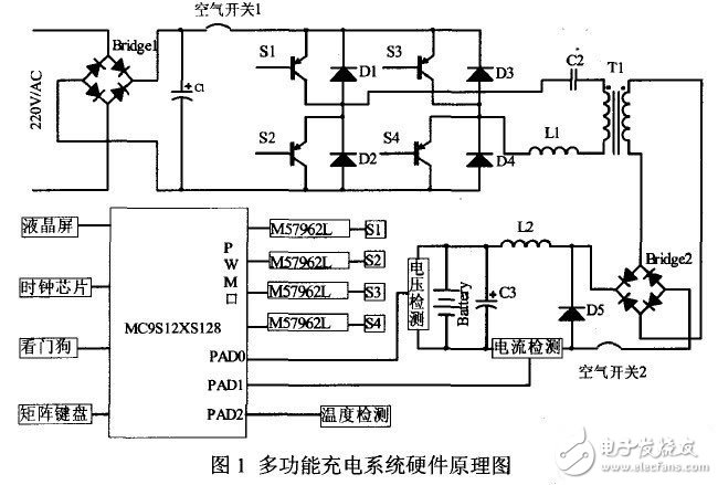
The system is mainly composed of the charging main circuit and the charging control circuit. Figure 1 shows the hardware schematic of the multifunctional charging system.

1.1 System Operation
This design uses a switching power supply technology, the maximum power of 3500W, the first 220V single-phase power frequency AC, after a full-bridge circuit composed of 4 diodes to rectify, and then after a large capacitor filter to get about 300V DC, at this time the DC ripple Larger. Direct current passes through a full-bridge inverter composed of four insulated gate bipolar transistors (IGBTs), and a high-frequency alternating current with adjustable voltage is obtained. The high-frequency alternating current is coupled to the secondary side via a high-frequency transformer, and then is rectified by a full bridge, and finally filtered by an inductance and capacitance. A small amount of direct current with a small ripple is used to charge the battery. The multi-function charging system can charge different types of batteries and batteries with different capacities. The charging voltage and current in the charging process are controlled in real time by a single-chip microcomputer. The entire charging system is a feedback control system, and the single-chip microcomputer detects the current and voltage in the charging process in real time. And temperature monitoring the entire charging process, effectively avoiding over-current, over-voltage and over-heating during the charging process, making the charging process safe and stable.
The air switch in front of the inverter bridge is to prevent a short circuit in the circuit or a large current to damage the battery or the electronic device. The MCU compares the charging current, voltage and temperature with the set value before charging, controls the output of 4 PWM waves to the gates of the 4 IGBTs, thereby controlling the collector-to-emitter current on-off time to reach the control output voltage. the goal of.

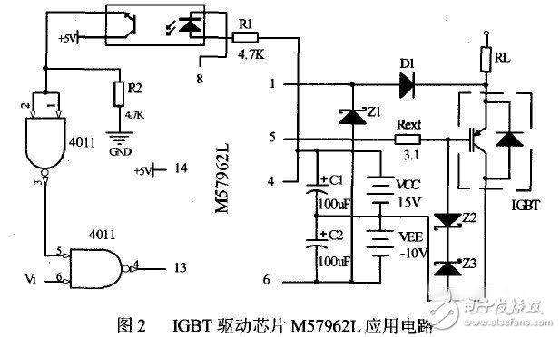
Since the IGBT needs to be isolated and driven, Mitsubishi's IBGT-specific driver IC M57962L is used in this design. Figure 2 shows its application circuit.
Due to the selection of 4 IGBTs to form a full-bridge inverter, each IGBT requires a M57962L chip driver, and each M57662L chip requires three voltage levels namely 15V, l0V, 5V to provide power, in which 5v voltage powers the MC9S12XS128 microcontroller at the same time This article designed a power transformer of 50W, which supplies power for the SCM and the four M57962L chips. The secondary winding outputs three sets of voltages. After rectification, filtering, and voltage stabilization, the required three voltages are obtained.
Wuxi Lerin New Energy Technology Co.,Ltd. , https://www.lerin-tech.com