In order to improve the stability of CNC machine tool processing, the machine tool is not interfered by external signals during processing. Use some necessary anti-interference measures to make the machine work normally and stably.
With the rapid development of CNC machine tool manufacturing, CNC machine tools have occupied a dominant position in large and medium-sized processing plants. The stability of machine tool processing during processing and the anti-interference measures of CNC machine tools in the design and manufacturing process have become common in CNC machine tool processing industry. Concerns.
CNC machine tools sometimes encounter various types of alarms during use. Some alarms are checked and do not meet the reasons explained in the maintenance manual published by the CNC system manufacturer. In fact, they are random alarms; the alarm numbers are not fixed or appear more Alarm number; or sometimes there is an alarm, sometimes there is no alarm, but the machine operation is strange and turbulent, so it is impossible to tell the cause of the alarm; sometimes the machine moves at low speed, returns to zero or shakes by hand The machine is not positioned correctly when the disk moves a few microns, and so on.
After discussions with system manufacturers and years of processing, it was found that more than 90% of these problems were caused by improper handling of electrical cabinets during machine tool manufacturing. Specifically, the design of the electrical cabinet is poor, and the grounding during the manufacturing and the wiring are unreasonable to cause the system to accept external interference.
1. Noise and interference of CNC machine tools There are several types of noise that cause interference to electronic equipment on the power grid:
1.1 Conductive noise
For example, noise generated by a servo amplifier can be transmitted through a cable to interfere with electronic equipment connected to the same power source.
1.2 Radiation noise
For example, noise generated by a servo amplifier can cause interference to surrounding electronic equipment through radiation from the power grid. The wires of the grid emit noise signals to the surroundings like a transmitting antenna.
1.3 induced (induction) noise (Induced noise)
Interference caused by coupling of induction or capacitance when the cable of the device is too close.
2. Anti-jamming measures of the machine tool These noises, if the wiring and wiring of the electrical cabinet are improperly handled during the design of the machine tool, will make the system unreliable due to interference. Based on experience and practice, some basic measures against interference are described below.
(1) The control system including the servo amplifier and the spindle drive unit shall be installed in a sealed metal cabinet.
(2) Pay attention to the wiring and wiring: the signal line and the power line should be separated separately, and the cable should be close to the metal wall of the electric cabinet.
(3) The signal line should be shielded. The command signal and the feedback signal line (such as the encoder signal) must be shielded and the shielded wire must be grounded.
(4) Controllers, amplifiers, and conductor devices (and materials) must be grounded.
(5) Add filters to the grid entry line and add surge absorbers.
(6) The driver of the electromagnetic coil of the contactor, relay or other appliance shall be equipped with a cremation absorber.
2.1 CNC controller power supply In order to be compatible, the current FANUCCNC controller power supply rate is 24V DC, generally using the 24V regulated power supply purchased on the market. Pay attention when selecting this power supply:
2.1.1 Capacity capacity should be sufficient. Take into account the capacity of the MDI keyboard and the capacity of the LCD or CRT. The power supply capacity should be the sum of the consumption of each printing plate in the controller + MDI keyboard consumption + LCD or CRT, and leave a certain margin (about +20%). If the capacity is not enough, the system may not work or work incorrectly.
2.1.2 Change rate from no load to full load With load, the power supply voltage should drop, and the required change rate should not be greater than 2%.
2.1.3 Output voltage deformation The output voltage cannot be intermittent. The components in the CNC controller are running at high speeds, and transient fluctuations in voltage can cause errors in their operation. It is required that the instantaneous interruption of the input voltage does not exceed the allowable value.
Pay attention when using the power supply:
(1) Do not connect the I/O point to the power supply. The I/O point of the machine's high-power control section must use another power supply.
(2) Pay attention to the order of power-on and power-off when using, especially the controller with gravity axis of the machine tool. Make sure that the drive motor of the gravity shaft is fully energy-damped and mechanically clamped before disconnecting the servo. power supply.
2.2 Power input line of the machine tool Transformer: When using the 200V type servo motor and spindle motor, the power supply incoming line needs to use a transformer. Due to the isolation of the transformer, the anti-interference ability is improved to some extent. In our country, according to the situation of the power grid, we need to choose the correct wiring type.
The grid filter, the noise filter, can be filtered out using a filter:
(1) Radiated noise from cables.
(2) Conducted noise due to stray (parasitic) capacitance.
Different capacity amplifiers (PSMs) use different filters.
Surge absorber: In order to avoid interference caused by lightning or other inrush equipment caused by nearby electrical equipment, the surge absorber should be connected to the incoming line. There are two ways for a surge absorber: between the lines of the grid and between the lines and the ground. The wiring of the surge absorber should be as short as possible, and the cross-sectional area of ​​the wire should be sufficient, about 2mm2.
AC reactor: AC reactor should be connected behind the main contactor (MCC).
Circuit breaker: The circuit breaker used should have leakage protection.
When using a 400V servo motor and spindle motor, the transformer can be eliminated. However, the use of transformers will increase the reliability of operation. When using a transformer, be sure to add a grid filter to the circuit.
2.3 Grounding of the machine tool The grounding system of the machine tool can be divided into: signal ground, chassis ground and system ground.
2.3.1 Signal Ground (SG)
This is the reference level (0V) supplied to the control signal.
2.3.2 chassis ground (FG)
A shield that isolates internal and external noise for reliable operation and immunity to interference. The shields of the casing, cover, mounting plate and interface cable of each unit shall be connected together.
2.3.3 System Ground (SG)
It is a protected area. The chassis of each device is connected to the ground to protect people and equipment from electric shock when there is leakage or short circuit, and interference noise can flow into the earth.
Pay attention when grounding:
(1) The signal ground (0V) on one unit is connected to the chassis ground (FG) only at one point.
(2) The casing of the signal system should be separated from the casing of the power section to avoid noise interference from the power section.
(3) The grounding point of the CAX1 of the power module should be connected to the chassis ground.
(4) The grounding wire should be thick enough to be at least as thick as the power supply cable.
(5) The grounding resistance (system ground) should be less than 100Ω.
2.4 The wiring, wiring and shielded cables in the machine electrical cabinet can be divided into high-power (power) signal lines and weak electric signal lines. The strong electric signal line includes: the input line of the amplifier, (source of information: http://) the power line of the motor, the contactor coil, the relay coil or other power signal line in the machine tool cabinet. These signals are 24V or more, DC or AC. The weak electric signal includes: a control signal line and a response signal line between the NC and the amplifier, a feedback line, a signal line of various sensors, etc., and these signals are 5V or less.
If the two lines are too close when the line is routed, as mentioned above, the strong signal will cause interference to the weak signal, so it is required:
(1) Must be separated: It is required to be bundled separately and separated by a certain distance.
(2) The weak signal line must be shielded and the shield must be grounded. There should be a grounding plate in the electrical cabinet. The shielding wires of each unit should be grounded through the grounding plate. The grounding plate of the strong electric (power) should be separated from the weak grounding plate and away from a certain distance. Do not share a grounding plate with other systems (such as plc controllers, material equipment, external inspection equipment, etc.).
2.5 Machine tool cabinet design (1) The cabinet must use metal materials, and the cabinet must be sealed. Because the sealed metal cabinet can isolate the electromagnetic radiation, the devices inside the cabinet are protected from interference. Of course, it is also possible to isolate the electromagnetic waves generated by the internal equipment during operation to avoid interference with external equipment. The grounded electric cabinet can also introduce leakage current into the earth, and the electrostatic field is grounded, thus ensuring that the cabinet body has zero potential, which protects the safety of people and equipment from electric shock.
(2) The joints are to be welded without gaps.
(3) The smaller the incision or opening, the better. The cover and door should be close to the cabinet with a conductive gasket.
(4) When connecting with the external conductor, the surface should be scraped and painted.
3. Summarize the stability of CNC machine tools plays an important role in the future mechanical manufacturing field. The implementation of anti-interference measures has a substantial effect on improving the stability of machine tools, and has a profound impact on the machining manufacturing industry.
Antenk DIN41612 Connectors are a versatile two piece PCB connector set with feaures useful for many applications including connections for plug-in card and back-panel wiring, PCB to PCB attachment and peripheral connections for external interfaces. Features include a multitude of body sizes and styles with options that include selective contact loading, make and break contacts, contact lead length choices and contact plating variations each in .100" [2.54mm] or .200" [5.08mm] centerline spacing.
The DIN 41612 standard covers a series of two-piece backplane connectors widely used in rack-based telecommunication, computing, process control, medical, industrial automation, test and measurement and military/aerospace systems where long-term reliability is required. They consist of one to three rows of contacts in combinations of 16, 32, 48, 64, or 96 contacts on a 0.1-inch (2.54 mm) grid pitch. The 3 rows are labelled a, b and c and connectors up to 64 way if using a 96 way body can use either rows a+b or a+c. DIN 41612 Signal connectors can be rated to 1.5 amps per signal pin, at 500 volts, although these figures may be de-rated according to safety requirements or environmental conditions. Several hybrid power and coaxial configurations are available that can handle up to 5.6A or even 15A. This wealth of variations explains the very wide range of applications that they`re put to. For over 30 years these DIN 41612 `Euro Card` connectors to IEC 60603-2 have offered a highly reliable system for board interconnects. Precision contact density, low mating forces, a two piece protective design and many contact termination styles offer unlimited design opportunities. Termination methods include – straight PC, solder eyelet, wire wrap, crimp and [press fit" terminals. Insertion and removal force are controlled, and three durability grades are available. Standardisation of the connectors is a prerequisite for open systems, where users expect components from different suppliers to operate together; ept and Conec DIN 41612 are therefore fully intermateable with all other similarly compliant products from other manufacturers like Harting, Erni, Hirose and TE Connectivity, etc.
The most common connector in the DIN product line is type C, which is widely used in VMEbus systems, the DIN 41612 standard has been upgraded to meet international standards IEC 60603-2 and EN 60603-2. In the past, ept used a comb supported press-fit tool for their type C and B press-fit female connectors. To be more competitive, ept has changed to flat-rock technology (just a flat piece of steel pushed on the top of the connector) as used by many other manufacturers.
DIN 41612 Connectors are widely used in rack-based electrical systems. The standard performance of these connectors is a 2 A per pin current carrying capacity and 500 V working voltage. Both figures may be variable due to safety and environmental conditions.
Types
Number of contacts varies
Many variations of housing material, including different types of metal and plastic
Both angled and straight versions
Male and female
C,R,B,Q Type DIN41612 Connectors
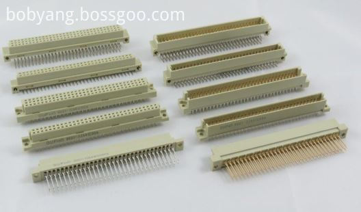
Half C, R, B & Q Type DIN41612 Connectors
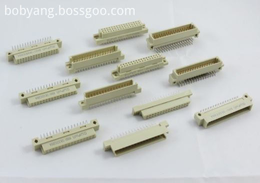
1/3 C,R, B & Q Type DIN41612 Connectors
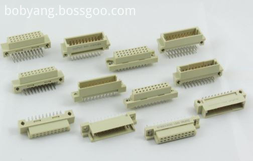
H, F, H+F & M type DIN41612 Connectors
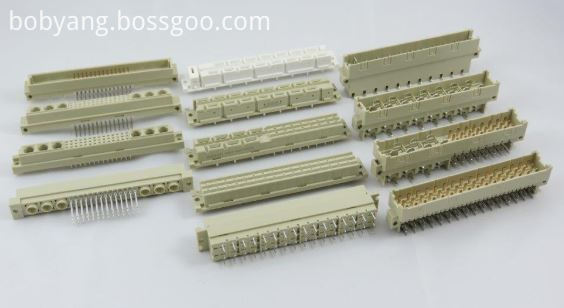
IDC Type DIN41612 Connectors
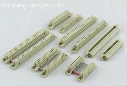
Female Cable Connector
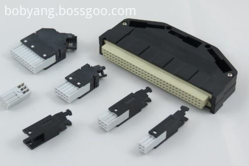
High Pin Count DIN41612 Connectors
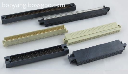
Shroud DIN41612 Connectors
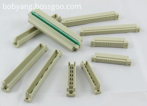
Features and Benefits of Din41612 Connector:
• Indirect mating (male/female)
• Automated production processes
• Continuous quality assurance
• 3-160 contacts
• Complete interconnection system
• Numerous interface connectors
• A wide variety of hoods
• Many termination technologies provide for the lowest installed cost
• Contacts selectively gold-plated
• Tinned terminations for increased solderability
Uses
The primary use of DIN 41612 connectors are PCB Connectors and motherboards, the main acceptance would be their board to board reliable connections.
Applications of Din41612 Connector:
Applications
• Data centers
• Storage
• Servers
• Base stations
• Telecommunications equipment
• Backplane and motherboard assemblies
• Switching systems
• Modular rack systems
• Power automation
• Distributed control systems in
industrial control
• Programmable logic controllers (PLC)
• Robotics
• Test and lab equipment
• Energy distribution
• Monitoring equipment
This is not a definitive list of applications for this product. It represents some of the more common uses.
Din41612 Connector,Din 41612,Eurocard Connector Din41612,Male Din41612 Connector
ShenZhen Antenk Electronics Co,Ltd , https://www.antenkcon.com