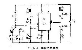
Figure 19.14 is a circuit for measuring resistance Rx. When W1 or W2 is changed so that the voltage of pin 6 of 555 is equal to or higher than two-thirds of the power supply voltage of 6V, C1 is continuously charged and discharged, and the voltage on C1 is at 6V of the power supply. One third of the fluctuations fluctuate, forming an oscillation, and LED1 and LED2 will alternately flash. When the 555 output is always high, LED1 is off and LED2 is always on. According to the above working principle, it can be used to measure Rx.
Switch K selects the range. When K is connected to A, the range is 5K ohms. When K is turned on, the range is 500K. The measured resistance is actually half of the resistance of W2 or W1. According to this range, W1 and W2 are scaled, and the indicated value of W1 and W2 is the Rx value.
The measurement method is: connect the measured resistor, select the range, adjust W1 or W2, observe the LED1 and LED2 illumination, make the two LEDs shine from the alternating flash, just become LED1 extinguish, LED2 shines, then W1 The indicated value of W2 and W2 is the resistance of the resistor Rx under test.

Replace 221 Lever Connector,Lever Connectors,Compact Connectors,Compact Splicing Connector
Guangdong Ojun Technology Co., Ltd. , https://www.ojunconnector.com