Overview:
From the perspective of protecting lead-acid batteries and improving charging efficiency, the shortcomings of the main charging methods on the market are analyzed, and a smart charger for positive and negative pulse type electric vehicles is designed. The system adopts PIC16F676 single-chip microcomputer to control, and the constant voltage phase in the ordinary three-stage charging mode is changed into positive and negative pulse; the middle charging mode increases the functions of trickle charging, optimizes the timing and self-power-off circuit, and extends the battery use. It has a good effect on life and shortening the charging time.
0 Introduction The current electric vehicle chargers mainly include the following: (1) Three-stage charger, which is divided into three stages: constant current, constant voltage and floating charge. The three-stage charging method can basically meet the needs of daily charging of electric vehicles, and the cost is also the lowest. However, this charging method has many problems. For example, the battery polarity of each manufacturer is different, it is easy to burn the charger and damage the battery; Floating state, etc. (2) Charger with anti-reverse connection and timing function, that is, when the polarity of the battery of the electric vehicle is reversed, it will not be charged to prevent malfunction; after the upper limit of charging time is reached, it will be forced into the floating state to prevent damage to lead acid. Battery. It can effectively prevent faults caused by different polarities, and can be forced into the floating charge phase, but it is controlled by thyristors or relays. The thyristors have an influence on the power grid. It is difficult to control the DC arc extinguishing by relays, which has potential safety hazards. (3) Pulse charger, the constant voltage phase in the three-stage charger is changed to pulse charging mode, but only positive pulse. This solves the problem of temperature rise during the charging process to a certain extent, and the charging efficiency is improved, but relying only on positive pulses is not ideal for solving these problems. Based on the above drawbacks, this paper designs an intelligent charger based on the three-stage charging circuit to improve the charging efficiency and prolong the battery life through a series of measures such as trickle charging, positive and negative pulse charging and timed power off. Repair a slightly damaged battery.
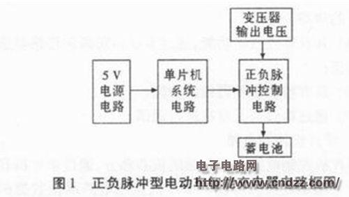
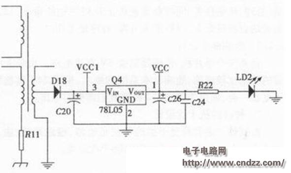
1 system hardware design The circuit of this scheme is mainly divided into three parts, which are the power circuit part, the circuit part of the one-chip computer system and the part of positive and negative pulse control circuit. As shown in Figure 1, the 5V power supply circuit is powered by a single-chip microcomputer. The single-chip microcomputer controls the output voltage of the transformer by controlling the positive and negative pulse control circuit to achieve the purpose of generating positive and negative pulses.


(Please read the PDF for details)
RAM/RFM electric heating capacitors
RAM/RFM Electric Heating Capacitors
Electric Heating Capacitor,Film Heating Capacitor,Electric Capacitor Bank,Induction Heating Capacitors
YANGZHOU POSITIONING TECH CO., LTD. , https://www.pst-thyristor.com