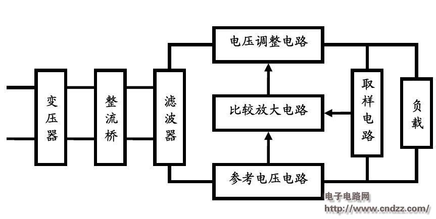
The first step: draw a circuit block diagram according to the working principle of the circuit, which is relatively easy, and is easier to obtain online than the circuit schematic. The more specific the block diagram is, the easier it is to convert the schematic. The following figure is a block diagram of a series regulator power supply:
Step 2: Turn the block diagram into a schematic:

The contents of each box are first changed to unit circuits.
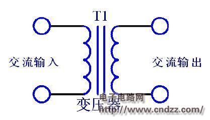
(1) Transformer: 
The schematic of the transformer is relatively simple, but the actual design is the most difficult part of the whole circuit.
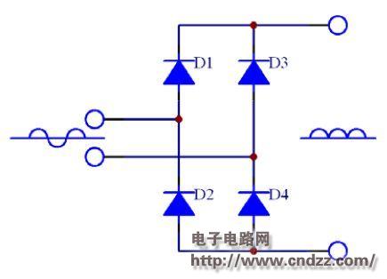
(2) rectifier bridge 
The rectifier bridge rectifies the sine wave to a voltage with only a positive half cycle, and the frequency becomes twice the previous one.
(3) Filter 
The filter circuit generally uses capacitors and inductors, and the capacitor is the simplest.
Using an inverting amplifying circuit, the control voltage is greater than the sum of the reference voltage and Vbe,
The triode works in the amplified state to control, and the control voltage controls the output voltage of Vout.
(4) Voltage adjustment circuit 
The Vce of the triode is variable to control the voltage division and keep the output voltage constant.
(5) Comparison amplifier circuit 
The inverting amplifying circuit is adopted, the control voltage is greater than the sum of the reference voltage and the Vbe, the triode operates in the amplified state to control, and the control voltage controls the output voltage of the Vout.
(6) Reference voltage circuit 
Vref is the reference voltage of the inverting amplifier, and the reference voltage is the voltage of the Zener diode.
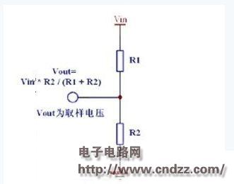
(7) Voltage sampling circuit 
The sampling circuit uses the simplest resistor divider circuit.
(8) Final combined circuit 
By combining the various parts of the block diagram according to the block diagram, the initial conversion of the circuit diagram can be completed.
It is also necessary to specifically analyze how the various parts are properly combined. These basic analyses are part of the circuit analysis.
The circuits in each block in the figure can be considered as a two-port network.
Capacitor For Power Transmission And Transformation
Capacitor for power transmission and transformation
New Parallel Capacitor 100Kvar,Capacitor Banks,High Voltage Capacitor Banks,Parallel Capacitor 200kar
YANGZHOU POSITIONING TECH CO., LTD. , https://www.cnpositioning.com