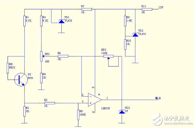
Circuit Description: The circuit consists of a detection circuit, a signal amplification circuit and a regulated power supply circuit. The detection circuit is composed of a resistor RH, a transistor VT and resistors R1 and R2; the signal amplifying circuit is composed of A1, RP1, RP2, R3, R4, R6, R5, R8, VD3; the regulated power supply circuit is composed of VD1, VD2, R7, R9, R10, R11, to provide 2.5V regulated power supply for the detection circuit. The resistor RH can be a silicon resistor because the response time of silicon is less than 5S at 25 degrees Celsius. Two TL431s are used in the circuit. The TL431 is a three-terminal adjustable shunt reference source with good thermal stability. Its output voltage can be arbitrarily set to any value from 2.5V to 36V with two resistors. The device's typical dynamic impedance is 0.2Ω, which can be used in many applications to replace Zener diodes, such as digital voltmeters, op amp circuits, adjustable voltage supplies, switching power supplies, and more.

Circuit principle: When the sensor is worn on the body, the RH resistance of the sensor is different due to the different temperature. This resistor becomes the base bias current resistance of VT. The difference in bias current makes the current at the base level different, thus changing the collector current of VT, which changes the VT emitter current. The current of the emitter flows through R2, and the emitter current is converted into voltage on R2. The voltage is sent to the non-inverting input terminal of A1, amplified by A1, and output voltage is controlled by VD3, so that the output voltage is within 5V.
flyphotography
SHAOXING SHANGYU FEIXIANG PHOTOGRAPHIC CO.,LTD , https://www.flying-photography.com