The content discussed today is to control the hardware peripherals on the ZedBoard board through the GUI software developed by QT. The complete signal chain is as follows: QT GUI → Linux Driver → AXI Bus → My_GPIO Peripheral → LED & Switch first establishes a QT Creator The QT GUI project, named my_gpio_gui, has the following interface, including the Label for displaying the status of the Switch, the text box for controlling the LED, a refresh button, and an exit button.
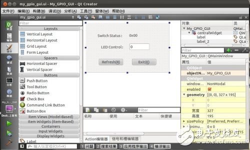
Then follow the method described in the sixth article to make an interface that can call the driver, but not C, but C++ (as long as it is not encapsulated, it is the same).
Portal: ZedBoard Learning Notes (6) The last step? Create a new C++ file called my_gpio_driver.cpp
by calling the driver from the upper application . The main code of the interface file includes two functions, one read register operation and one write register operation. The read operation register operation code is as follows: int Read_Regs(int reg_num){ int my_gpio_fd = 0; char rd8_buf[4]; int rd32_buf; QMessageBox msg; my_gpio_fd = open("/dev/my_gpio_dev", 0); if(my_gpio_fd<0 ) { msg.setText("[ERROR] Can't open device."); msg.exec(); return 0; } if(read(my_gpio_fd, rd8_buf, sizeof(rd8_buf)) != sizeof(rd8_buf)) { msg.setText("[ERROR] Read bytes no correct."); msg.exec(); } rd32_buf = (int)rd8_buf[reg_num+0] + ((int)rd8_buf[reg_num+1]<<8) + ((int)rd8_buf[reg_num+2]<<16) + ((int)rd8_buf[reg_num+3]<<24); close(my_gpio_fd); return rd32_buf;} C program call as described here and in the previous blog The only difference in the driver is that there is no command line under QT's graphical interface, and it is impossible to print error messages through printf. So the rabbit defines a QmessageBox dialog, which sets the content to be displayed in the dialog via the setText property, and displays the dialog via the exec() method. If necessary, you can further wrap it, for example, use Get_SW_Status and Get_LED_Status to mask the specific registers: int Get_SW_Status(){ return Read_Regs(0);} int Get_LED_Status(){ return Read_Regs(1);} Write operation is the same , but only need to write a register here, so there is no need to do the packaging, one step in place. Void Write_LED_Data(int led_dat){ int my_gpio_fd = 0; QMessageBox msg; my_gpio_fd = open("/dev/my_gpio_dev", 0); if(my_gpio_fd<0) { msg.setText("[ERROR] Can't open device. "); msg.exec(); return; } ioctl(my_gpio_fd, 1, led_dat); close(my_gpio_fd);} Save my_gpio_driver.cpp and add it to the project, and write the corresponding header file my_gpio_driver.h. Open the edit my_gpio_gui.cpp, reference my_gpio_driver.h, and add a signal slot to the two buttons in the interface as described previously. The code for the refresh button is as follows: void My_GPIO_GUI::on_pushButtonRefresh_clicked(){ ui->label_SW->setText(QString::number( Get_SW_Status(), 16)); Write_LED_Data(ui->text_LED->text().toInt() ); } The meaning is very simple, that is, whenever the refresh button is pressed, the data in the Switch status register is read out, displayed in hexadecimal form on the label_SW label, and then the string in the text_LED text box (actually Converted to an integer for several decimal digits, written to the LED control register. Use the close() method in the exit button to close the entire GUI program: void My_GPIO_GUI::on_pushButtonExit_clicked(){ this->close();} After the code is modified, run it on the PC and find that the error dialog box pops up when the refresh button is pressed. : "[ERROR] Can't open device", this is because there is no my_gpio driver module on the PC device. Using qmake and make to cross-compile the entire project will generate a My_GPIO_GUI executable file, copy it to the ZedBoard, and it will run. Of course, you must load the my_gpio driver module and the qt_lib.img runtime library before running. It is then executed in the executable directory via the My_GPIO_GUI –qws directive. The effect of this software is that each time the refresh button is pressed, the LED status changes according to the data entered in the text box, and the upper label shows the status of the Switch on the current board. Attach the complete project:
My_GPIO_GUI.rar last picture:
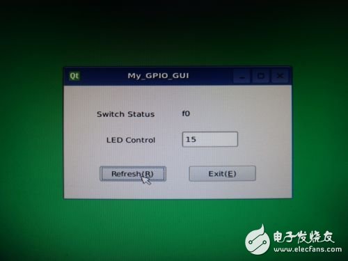
Set parameter LED=0x0F, SW=0xF0
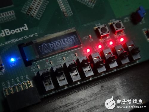
Rendering
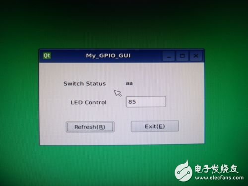
Set parameter LED=0x55, SW=0xAA
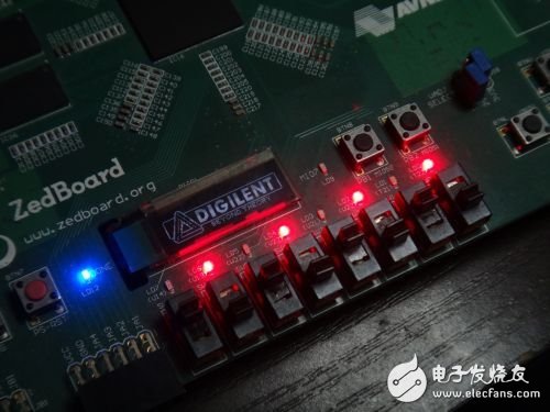
How about the effect chart, have you found that these operations are actually learned in the past, when all aspects of knowledge are available, the integration is really easy, the previous efforts are valuable. Now you have mastered the custom acquisition IP from the AXI bus, to the Linux driver, and then to the QT graphical user interface software, a complete acquisition and control data chain design method. But the rabbit's study notes are just an introduction. The logic, the driver, and the upper software have their own knowledge. They all need patience and perseverance to learn in depth. At the same time, they need to learn through practical operations. As Mr. Yu Qiuyu said, reading Wanli Road, Wanjuan Road, this Wanli Road is to go back and look at the book to see if it is true or not. If there is any delay, how should it be corrected? This is Good learning method. After mastering the basic methods, what remains is the entire vast world of All Programable. How to make color depends on how you are imaginative.
Renewable Energy Cable Assembly
Kable-X has passed ISO9001 quality system certification, UL certification, ISO13485 medical quality system certification, ISO/TS16949 automotive quality system certification, etc. How to implement these system certifications into the actual production process? Harness product quality control involves design, Production, procurement, quality and other departments must create a team quality culture. Product quality is the life of the company. Through meetings, problem discussions and other forms, employees are constantly instilling quality awareness. We have weekly meetings on Mondays, morning meetings for production line teams, and customers. Regular product meetings and so on. Only through continuous learning, improve the quality awareness of team members, and improve the execution of the entire team, can we continuously improve the level of quality control. There is no end to quality control, there is no best, only better.
Only through strict waterproof wiring harness design, purchase of waterproof wiring harness produced by regular manufacturers, production in strict accordance with waterproof wiring harness technology, and rigorous and thorough quality inspections, can we produce qualified defensive wiring harness.
We produce a large number of Renewable Energy Cable Assembly, among which BMS Sampling Wire Harness and Energy Storage Wire Harness are loved by many customers. In addition, we also produce Medical Cable Assembly and Renewable Energy Cable Assy.

Renewable Energy Cable Assembly,Renewable Energy Cable Assy,Renewable Energy Cable Harness Assembly,Renewable Energy Medical Cable Assemblies
Kable-X Technology (Suzhou) Co., Ltd , https://www.kable-x-tech.com


