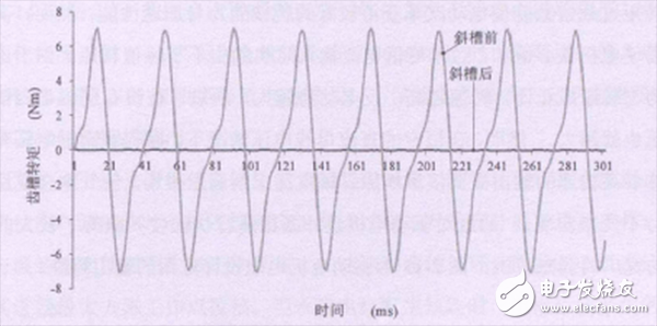
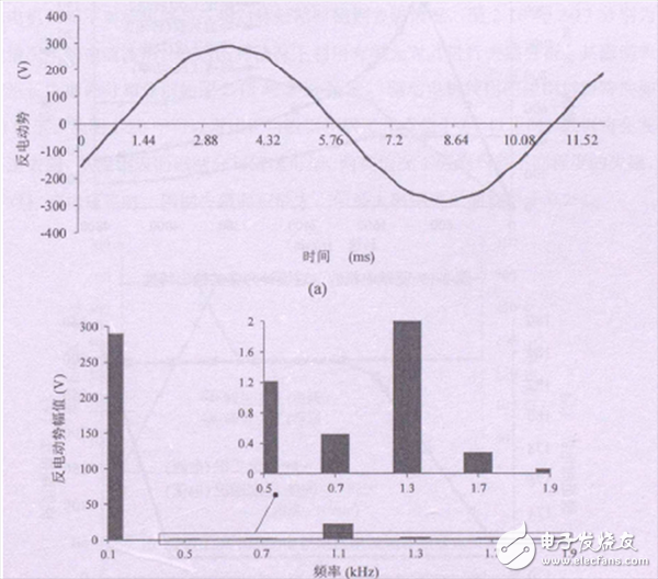
In order to ensure the accuracy of the calculation, it is necessary to analyze and check the electromagnetic performance of the drive motor. Here, the finite element method is used to analyze and calculate the driving motor under the conditions of no-load, torque overload, high-speed weak magnetic and short-circuit demagnetization. The interaction between the magnetic steel and the slotted armature core in the permanent magnet motor causes the air gap flux to change, which inevitably produces cogging torque, which causes torque ripple, noise and vibration, which will further affect the entire system. control precision. Many methods for weakening the cogging torque have been proposed, such as chutes, oblique poles, optimized slot openings, optimized pole arc and magnetic steel shapes. The chute method not only has mature driving technology, simple production process, and good effect, but also the back electromotive force waveform obtained is extremely sinusoidal. Figure 1 is a comparison of the cogging torque between the front and rear of the drive motor chute. The front cogging torque of the chute accounts for 2% of the electromagnetic torque at the total rated load. After the chute, the cogging torque is basically weakened. At 1500r/min, the calculation result of the back electromotive force of the drive motor is shown in Fig. 2. Since the chute makes the back electromotive force more sinusoidal, its harmonic content is greatly reduced.

Figure 1: Cogging torque diagram of the drive motor

Figure 2: Calculated value of back electromotive force
The high torque overload factor enables electric vehicles to achieve better gradeability and acceleration performance. However, it is easy to saturate the motor core during high torque overload, so that the peak torque cannot be output when the peak current is input. Since the motor no-load counter electromotive force is proportional to the rotational speed, the higher the rotational speed, the larger the back electromotive force, so the motor terminal voltage is greater without the weak magnetic current. However, in the case of a constant DC bus voltage, the controller output voltage has an upper limit, which means that the output of the high speed needs to be increased by increasing the d-axis current to weaken the main magnetic field and keeping the air gap synthesis back electromotive force substantially unchanged.
The irreversible demagnetization of the magnetic steel will weaken the performance of the global motor including the rated voltage and rated power, thus affecting its normal use. If the motor is still working according to the design requirements of the rated working condition or the overload working condition, the demagnetizing armature magnetic potential and temperature rise will make the demagnetization of the magnetic steel more serious and accelerate the vicious cycle. Therefore, it is necessary to perform the maximum demagnetization working point check for the motor design. When the permanent magnet motor is short-circuited, the magnetic potential generated by the armature reaction is almost a straight-axis magnetic potential of pure demagnetization. Therefore, the demagnetization analysis of the magnetic steel should focus on such a situation. From the magnetic dense distribution on the surface of the magnetic steel, it can be known that the magnetic steel has different degrees of demagnetization in both cases. In the case of asymmetric three-phase short circuit, the demagnetization area of ​​the magnetic steel is the largest, but the maximum demagnetization area of ​​the magnetic steel is less than 0.2%.
The entire drive motor test system mainly includes DC power supply, drive motor, brushless controller, cooling water system, torsion sensor, power analyzer and oscilloscope. The main function of the DC power supply is to rectify the three-phase AC power in the power grid into a controller of the DC input drive motor for use in the test system. In the motor test, two drive motors were used to test the drag. One of the motors acts as a motor and the other acts as a generator. The driving motor cooling water is supplied by the cooling water tank, and the cooling water is first drawn into the driving motor by the external water pump to cool it, and finally flows into the cooling water tank to circulate. The controller uses forced air cooling for cooling.
Portable Energy Storage System
Portable power supply humanized output port design: AC dual output port 220V output, to solve multi-channel power demand; DC 24V, 12V cigarette lighter, dual 5V USB output, more widely used. Can meet the needs of most electrical appliances, such as energy storage system for LED Light,energy storage system for outdoor, energy storage system for medical equipment,mobile phones, telephones, digital cameras, mobile hard drives, digital cameras, tablets, laptops, car starters, pumps, postal and telecommunications, environmental instruments Etc; can also be used in the following areas such as: finance, first aid, excavation, exploration, military, science, media, tourism, disaster relief, medical assistance, environmental protection and areas with widespread power shortages.
Portable Storage,Ac Rechargeable Battery,Portable Energy Storage System,Outdoor Portable Energy Storage System,Portable Battery With AC/DC Output,High Capacity Portable Battery
Shenzhen Enershare Technology Co.,Ltd , https://www.enersharepower.com