The Sterling Bridge is a circuit that is ideal for measuring the amount of resistance accurately. Although it has been invented for nearly 150 years, it is still favored by electronic engineers for its extremely high test accuracy.
What is the working principle of the bridge?

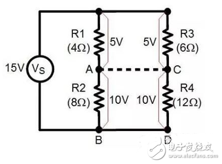
Look at this simpler way of understanding. In this drawing, there are two branches: R1 and R2 form one, and R3 and R4 form one. According to the resistance value on the drawing, the voltage between R1 and R3 will be equal, and the voltage between R2 and R4 will be equal. This is because the ratio of the resistance values ​​between R1 and R2 is equal to the ratio of the resistance values ​​between R3 and R4, so the voltages they share are also equal. This makes the potentials of points A and C the same. If you wire A and C together, there is no charge flow between the two points. At this time you can call the bridge balanced.

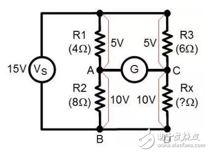
Now let's assume that the value of resistor R4 is unknown (and set it to Rx) and connect an ammeter to the A and C points in the previous circuit. If the current indicates that the number is 0, we can immediately get the value of the resistor Rx - because, as mentioned above, when there is no current flowing between the two points of AC, the voltage at the two points of the AC must be the same, so R1 and R2 can be obtained. The ratio between the resistance values ​​and the resistance values ​​between R3 and R4 are also equal. The resistance value of Rx can be calculated. Rx=(R2 x R3)/R1.
But what if we don't have a zero G, what should we do? At this time, the voltage at the two points of AC is definitely not equal. We can replace R2 with a variable resistor and repeat the test. In the experiment, turn on the power and start to adjust the variable resistor. Note that in the previous figure, points B and D are actually the same points in the circuit, so we can draw them together. In the process of adjusting the resistance, you will find that the indication of the ammeter changes, and after adjusting to the current meter, there is no indication that the state is the same as that in the first case. At this point, you can substitute the resistance of the variable resistor and calculate the resistance value of Rx according to the calculation formula in the first case.
What can the bridge do?

In fact, by calculating the voltage difference between the two points of AC in the schematic, you can directly calculate the resistance of an unknown resistor by the resistance of three known resistors. The advantages of this calculation are mainly two: you can pass this The method measures the resistance of a hard-to-reach position, such as the resistance of a temperature-measuring resistor buried in concrete. On the other hand, the accuracy of such measurements is also higher than that of the meter when measuring resistance directly. For smaller resistance values, we no longer need to amplify them. Instead, with the help of the other three higher precision resistors, we can directly calculate the high resistance by directly using the difference in voltage. .
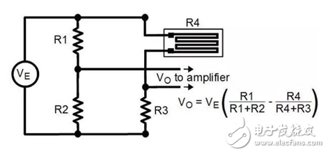
A more classic application is to measure small stress changes. The reflection of all stress changes on the stress sheet is a very small change in the resistance of the stress sheet when it is bent. This stress sheet is mainly buried deep inside the building or bridge to detect changes in internal forces.

When measuring resistance, we also use a bridge circuit to convert the change in resistance value into a change in voltage value and send it to the amplifier. The resistance value can be obtained by measuring the voltage value. This measurement method is very common and effective.
Understand the principle of the bridge, when designing the temperature sensitive or photosensitive circuit next time, understand what method to measure the small amount of resistance?
Lithium Battery Pack For Hybrid Electric Locomotive
Lithium Battery For Electric Car,Cylindrical Battery,2000-2500Kw Lifepo4 Battery System,Ce Certificated Lithium Battery
Henan Xintaihang Power Source Co.,Ltd , https://www.taihangbattery.com