This system requires the design and manufacture of a simple intelligent electric vehicle. The design includes basic requirements, part and other innovative parts.
basic requirements
1 The electric car starts from the starting line (the car body must not exceed the starting line) and reaches the point B along the black guide line with a width of 2 cm. One or three thin iron pieces each having a width of 15 cm and a length are buried along the guide line under the white paper laid in the "straight road area". When the electric vehicle detects the thin iron piece, it immediately emits the sound and light indication information, and stores and displays the number of thin iron pieces detected in the “straight track area†in real time.
2 When the electric vehicle reaches point B, it enters the “curve area†and reaches the point C along the arc guide line (it can also leave the arc guide line to reach point C). A square thin iron piece with a side length of 15 cm is buried under point C. The electric vehicle is required to reach the point C to detect the thin iron piece and then stop at C for 5 seconds, and intermittent sound and light information is issued during the stop.
3 Under the guidance of the light source, the electric vehicle enters the parking area through the obstacle zone and arrives at the garage. Electric vehicles must pass between two obstacles and must not be in contact with them.
4 The electric vehicle will stop immediately after completing the above tasks. The whole journey must not exceed 90 seconds. When the driving time reaches 90 seconds, it will automatically stop immediately.
Line tracking circuit
Solution 1: CCD monochrome camera with computer motherboard and image capture card. Under the white background, the recognition of the black line is relatively mature and the effect is quite good. But the cost is high and it is difficult to find a suitable carrier.
Option 2: Use a color sensor. At present, the application of color sensors is more and more extensive, and the effect is also ok. But a few hundred dollars in price and relatively complex processing circuits, but also need a light source, so it is not a good choice.
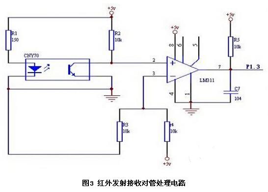
Option 3: Use one left and one right infrared to receive the pair of tubes. The sensor is not only cheap, easy to buy, but also the processing circuit (shown in Figure 3), simple and easy to use, the actual use is very good, can smoothly guide the car to point C.
In this circuit, the purpose of adding the comparator LM311 is to convert the analog quantity into a switching quantity for easy processing. In order to make the transmission have a certain power, the transmitting circuit requires a current of not less than 20 mA.
According to the choice, R1=150Ω can be selected.
At the start, the car straddles on the black line. Two infrared transmitting and receiving pairs are respectively installed in the white areas on both sides of the black line, and the output is a low voltage. When the deviation is on the black line, the output is a high voltage. Because the black line is narrow (2cm), in order to adjust the direction of the car in time, the threshold of the comparator is selected to be 2.5v, that is, the position between black and white, that is, the adjustment is started. Experiments show that the effect is ideal
Obstacle avoidance circuit
Solution 1: Use laser sensor to measure distance. It can accurately measure the distance between the car and the obstacle, but the price is also high, the processing is complicated, and it does not meet our requirements.
Option 2: Use an ultrasonic sensor. The imported ultrasonic sensor has a thin transducer and a processing circuit, and outputs an analog signal proportional to the distance. The AD information can be used to obtain the distance information, which is expensive. There are also some simple ultrasonic sensors and processing circuits that can output switching information, and the price is not expensive. It is a good choice, but since there is no ready-made processing circuit, it has not been done in this way, and the time is tight. Therefore, it has not been adopted.
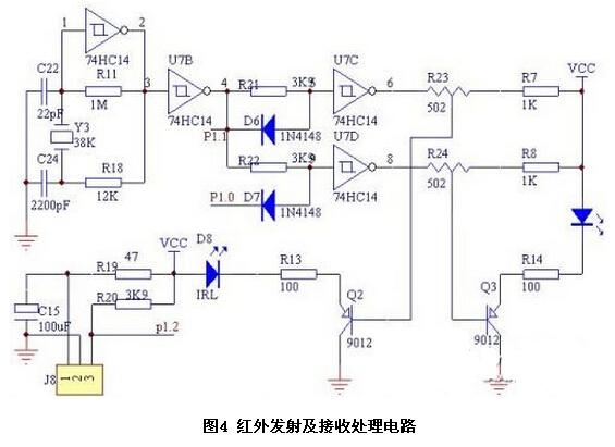
Option 3: Use two left and right infrared sensors. Infrared sensor is a kind of obstacle avoidance sensor which is commonly used at present. Its processing circuit is shown in Figure 4. By adjusting two potentiometers R23 and R24, the detection distance of two infrared sensors can be adjusted to 10-80cm. Output (TTL level), simple and reliable. We use this circuit to reliably detect obstacles in the front left, right front, and front, providing a guarantee for successful obstacle avoidance.
Light source detection circuit
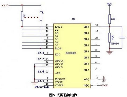
In order to detect the intensity of the light, we added two photosensors, the photoresistor, to the front left and right of the cart. The circuit is shown in Figure 5. The photosensitive sensor changes according to the intensity of the light irradiated on it, and the output voltage changes accordingly. After passing through ADC0809, a digital quantity corresponding to the light intensity is obtained, thereby guiding the trolley to approach the light source. Different types of photoresistors, dark resistance and bright resistance have large differences. It is necessary to select different size divider resistors according to different parameters of the photoresistor.
Metal detection circuit
A vortex type iron metal detection sensor is used, model: LJ18A3-8-Z/BX. Reliable detection distance, less than 8cm.
Motor drive circuit
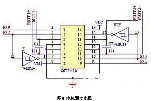
The commutation and drive circuit of the electric car itself is quite rough, and the characteristics of the motor are also very bad, and the speed can not be adjusted. The voltage is low, the speed is slow, the driving torque is small, and the driving is not moving; when the voltage is high (just when the battery is replaced), the speed is fast and difficult to adjust. On this, it took a lot of time and the effect was very bad. Finally, it was decided to replace the motor and drive circuit of the car. The rear wheel uses a pair of decelerating DC motors, and its drive circuit is shown in Figure 6. PWM control makes it easier to adjust the motor speed.
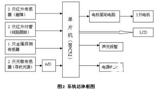
The simple intelligent electric vehicle was transformed from an electric toy car. The control part of the system takes the single-chip microcomputer as the core. Through the acquisition and processing of various sensor signals of the forward channel, the motion control of the backward channel drive and steering motor and the processing, display and sound and light alarm of related information are better realized.
9 in 1 usb c adapter,10 In 1 Usb C Hub,usb-c multifunction adapter,type-c all-in-1 adapter macbook,USB C HUB,best USB-C Hubs
Shenzhen Konchang Electronic Technology Co.,Ltd , https://www.konchangs.com